218
BIT7 Reserved
BIT8 Reserved (servo running)
BIT9 Reserved (customized running)
BIT10
Reserved (synchronized speed
running)
Others Reserved
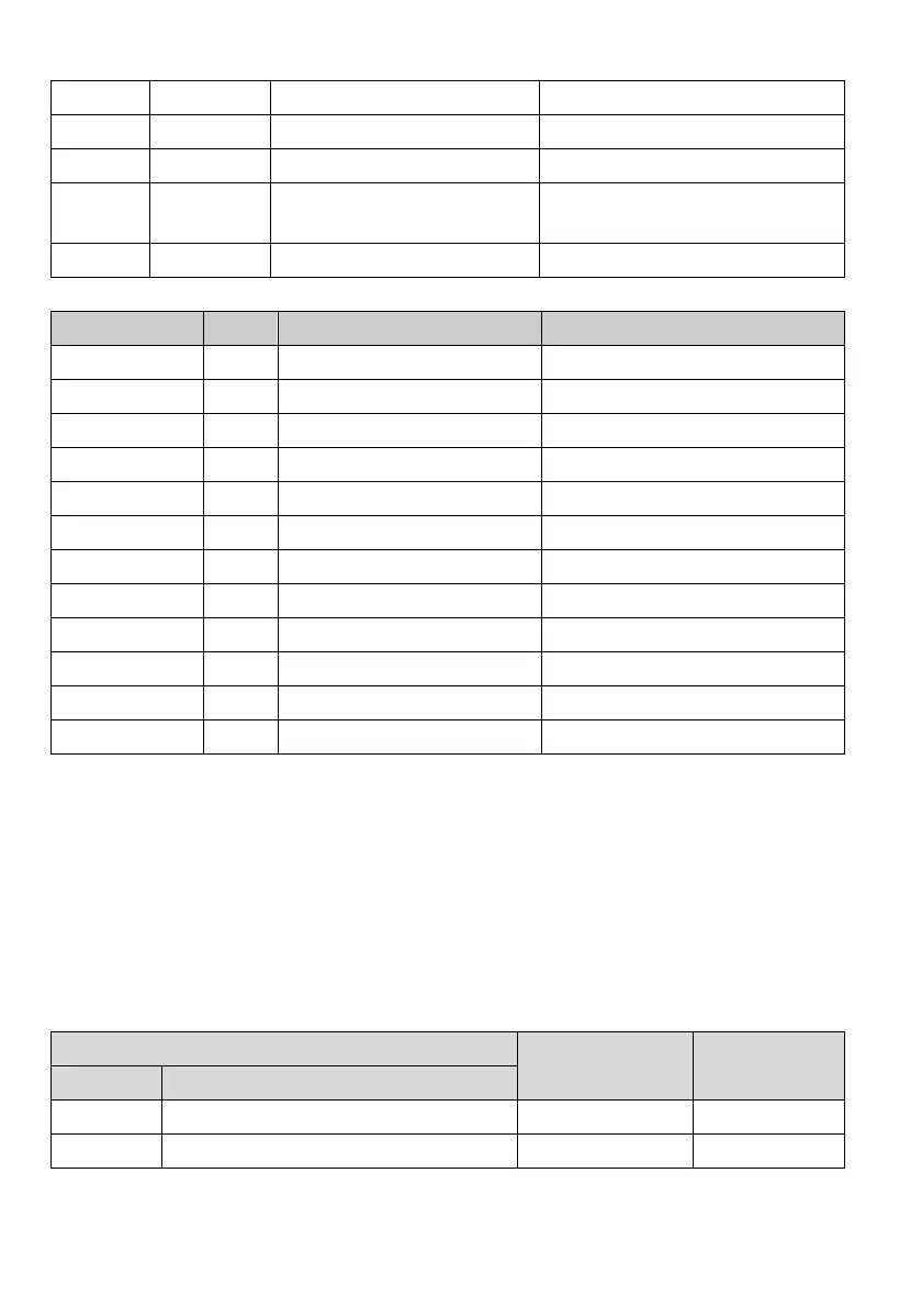
The bit definition of the status word 3 of the drive is as shown in the following table:
Bit Value Function Remarks
BIT0~BIT1 Reserved
BIT2 Running at zero speed
BIT3 Accelerating
BIT4 Decelerating
BIT5 Running at constant speed
BIT6 Pre-exciting
BIT7 Setting
BIT7 Setting
BIT8 Limiting over-current
BIT10~ BIT11 Reserved
BIT12 Drive fault
BIT13~BIT15 Reserved
7. Expand access mode
The standard protocol only supports the register of 16 bits, and the above description is also based on the
register of 16 bits. The parameters of MV200 series drive include both 16 bits (single character) and 32 bits
(double characters). So, the data of both lengths shall be considered when reading/writing the parameters.
There are two modes in which the drive parameters are accessed to, including 16-bit mode and 32-bit mode,
that is, the user can read/write the parameters with 16 bits or 32 bits as the unit separately. The 16-bit mode
and 32-bit mode are identified through the “start register address” of the request frame. If the highest byte of
the address is 0, the reading/writing shall be done in the 16-bit mode, otherwise, they shall be done in the
32-bit mode. As shown in the following table.
Start register address
Access mode Remarks
BIT15 BIT14~BIT0
0 Actual address of the start parameter 16-bit
1 Actual address of the start parameter 32-bit
When accessing to the parameters in the 32-bit mode, as the unit of the register of the request frame is 16 bits
and each parameter of 32 bits needs two registers of 16 bits, the “number of registers” shall be set correctly.
 Loading...