10
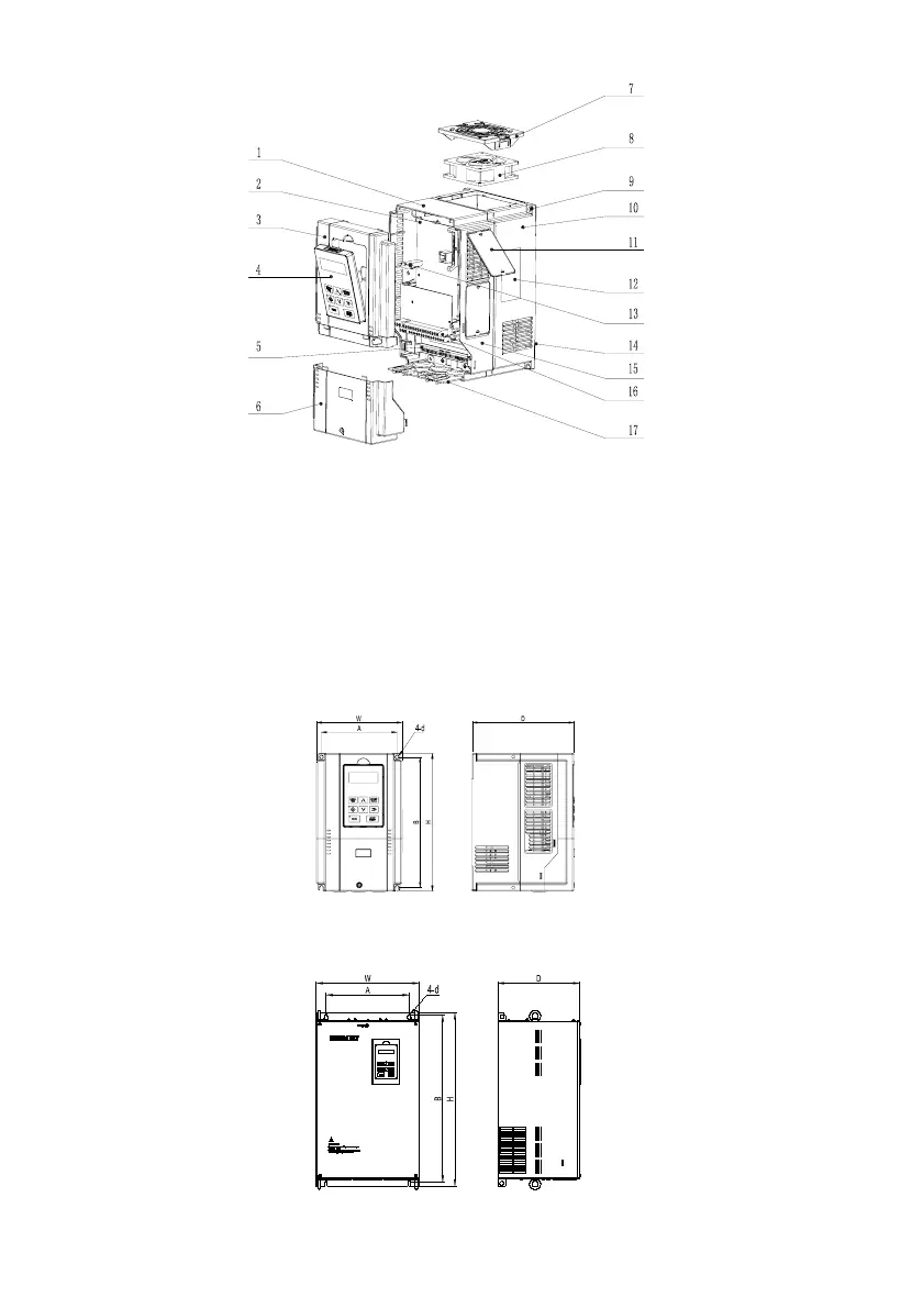
1. Mid-enclosure 2. Main control board 3. Upper cover 4. Operation panel 5. Main circuit wiring terminal
6. Lower cover 7. Fan guard 8. Fan 9. Mounting holes for complete unit 10. Bottom enclosure 11. Dustproof plate
12. Nameplate 13. Connector 14. Bottom plate 15. Mid-enclosure 16. Control terminal 17. Wiring plate
Fig. 1-1 Drive structure (taking R4 as an example)
1.6 Outline, mounting dimensions and gross weight of drive
There are four types of outlines as shown in Fig. 1-2, Fig. 1-3, Fig. 1-4 and Fig. 1-5. The outline, mounting
dimensions and gross weight are as shown in Table 1-4 and Table 1-5.
1. Enclosure R2~R4 ( G: 5.5kW-18.5kW; P:5.5kW-18.5kW)
Fig. 1-2 Outline, mounting dimensions for products of R2~R4
2. Enclosure R5~R8 (G: 22kW-132kW; P: 22kW-132kW)
Fig. 1-3 Outline, mounting dimensions for products of R5~R8
 Loading...