120
The meanings of the above motor parameters are shown in Fig.6-9.
R
1
jX
11
R
2
jX
21
I
1
I
2
I
0
X
m
U
1
1-S
S
R
2
Fig.6-9 Equivalent circuit diagram for asynchronous motor in steady state
The R
1
, X
11
, R
2
, X
21
, X
m
, I
o
in Fig.6-9 respectively indicate the stator resistance, stator leakage inductive
reactance, rotator resistance, rotator leakage inductive reactance, mutual inductive reactance and
no-load current. Function code P03.07 is the sum of leakage inductive reactance of the stator and rotator.
If the parameters of the asynchronous motor are known, please write the actual values into
P03.06~P03.09. P03.10 is the no-load current of asynchronous motor. You can directly enter the no-load
current value.
If the motor parameter auto-tuning is conducted, the set values of P03.06~P03.10 will be refreshed after
the normal completion of the auto-tuning.
After changing the motor power P03.00, the drive will set the parameters of P03.02~P03.10 to be the
default parameters of the motor. (The rated voltage of motor 1 (P03.01) needs to be set according to the
nameplate by the user).
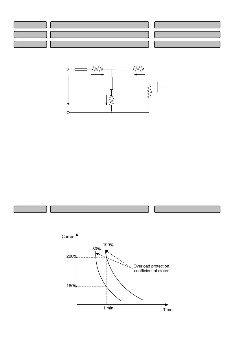
To provide effective overload protection for motors of different models, it is necessary to adjust the
allowable maximum output current of the drive, as shown in Fig.6-10.
Fig.6-10 Overload protection coefficient setting of motor
Overload protection coefficient of motor 1
20.0~110.0%
100.0%
P03.11
No-load current (I
0
) of motor 1
0.1~999.9A(depending on
P03.10
Mutual inductance of motor 1
0000.0~2000.0(depending on
P03.09
Rotator resistance of motor 1
00.000~65.000(depending on
P03.08
 Loading...