170
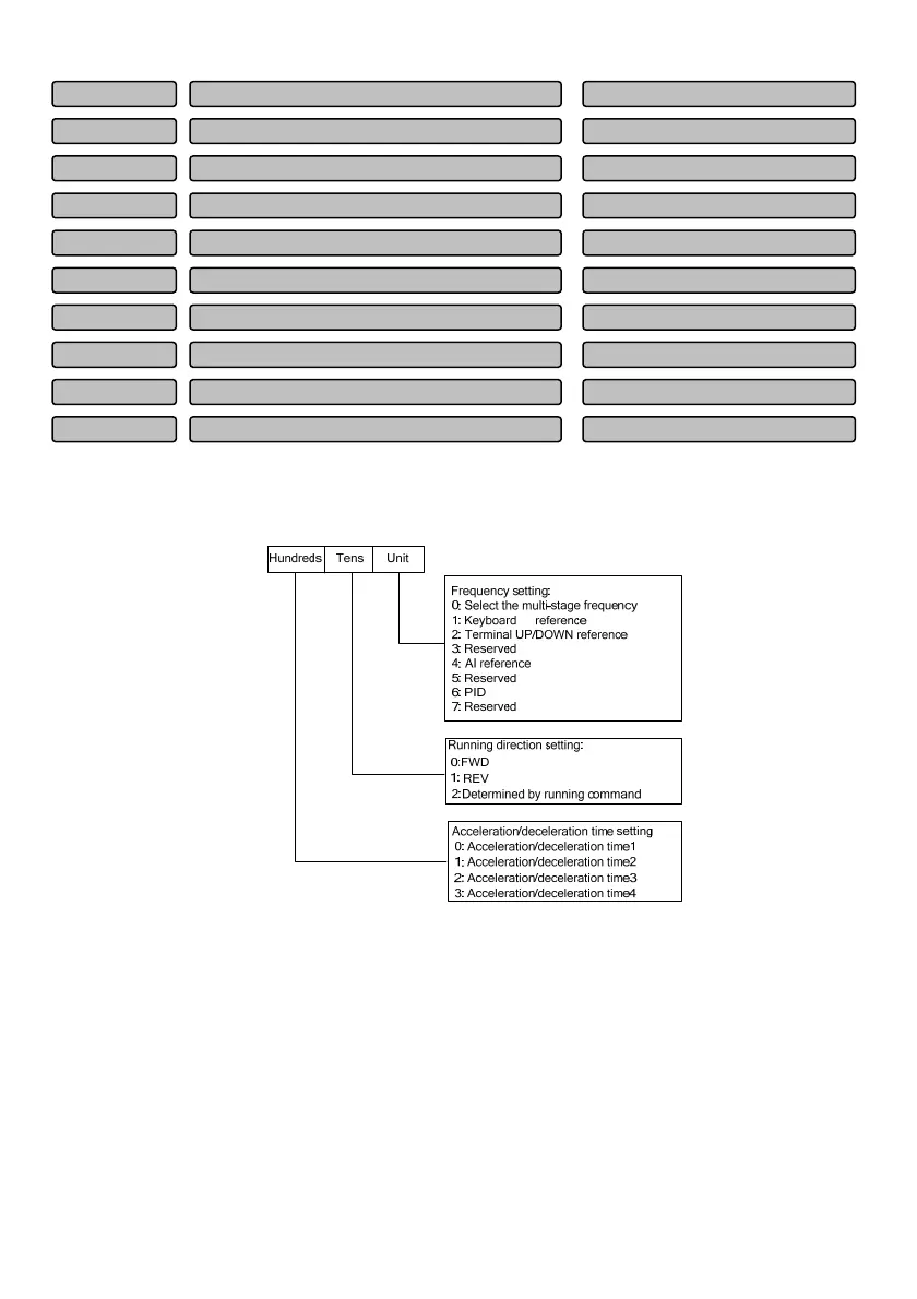
P13.17, P13.19, P13.21, P13.23, P13.25, P13.27, P13.29, P13.31, P13.33, P13.35, P13.37, P13.39,
P13.41, P13.43 and P13.45 are used to configure the running frequency, direction, acceleration /
deceleration time for each stage of the PLC, and they are selected by bits. As shown in Fig.6-58.
∨∧
Fig.6-58 Setting of PLC stage
Unit place of LED setting of the PLC i stage:
0: Select the multi-stage frequency i
For example, when i=3, the frequency of stage 3 is the multi-stage frequency 3. For the definition of the
multi-stage frequency, please refer to P13.00~P13.46.
1: Digital reference 1: Keyboard
∧∨ reference
2: Digital reference 2: Terminal UP/DN reference
3: Reserved
4: AI analog reference
Sta
e 15 runnin
time 0.0~6500.0
20.0
P13.46
Sta
e 15 settin
0~327H
000
P13.45
Sta
e 14 runnin
time 0.0~6500.0
20.0
P13.44
Sta
e 14 settin
0~327H
000
P13.43
Sta
e 13 runnin
time 0.0~6500.0
20.0
P13.42
Sta
e 13 settin
0~327H
000
P13.41
Sta
e 12 runnin
time 0.0~6500.0
20.0
P13.40
Sta
e 12 settin
0~327H
000
P13.39
Sta
e 11 runnin
time 0.0~6500.0
20.0
P13.38
Sta
e 11 settin
0~327H
000
P13.37
 Loading...