Basic Operation and Installation
Rev 3.4
Mellanox Technologies
34
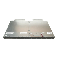
Figure 23: Connect Bracket to Rack Vertical support
9. Place the four bolts for the caged nuts within reach.
10.Slide the switch into the rails.
11. Put the switch into place and screw the bolts into the nuts from step 6. If the power cable is on
this side of the switch, feed the power cable into the slot in the bracket before screwing it to the
vertical support.Tighten the bolts to 9.2 Nm or 81.5 pound inches.
12.Tighten all of the screws to 9.2 Nm or 81.5 pound inches.
13.Ground the switch
14.Plug in the power cables.
15.Check the Status LEDs and confirm that all of the LEDs show status lights consistent with
normal operation.
16.You can start connecting all of the cables to the switch.
3.6.3 Grounding the Switch
Check to determine if your local or national electrical codes require an external ground to all IT
components. If so, connect a ground wire to one of the casing screws and connect the other end to
a valid ground. If you choose to not use the ground screw, make sure that the rack is properly
grounded and that there is a valid ground connection between the chassis of the switch and the
rack. Test the ground using an Ohm meter.
Warning: Any yellow status LEDs is cause for concern and must be dealt with imme-
diately.
It can take up to 5 minutes to boot up, during which time the status LED may indicate
red.
Some national and/or local codes may require IT components to be bonded and exter-
nally grounded (not including the power cord ground). You must follow all national
and local codes when installing this equipment.
 Loading...