Electrical System
Page 8A-6 90-863758060 AUGUST 2006
3.7–4.6 m (12–15 ft.)
95 mm
2
(000)
4.6–5.8 m (15–19 ft.)
120 mm
2
(0000)
• Multiple engine installations (including generator sets) require that a negative cable be
run between the engines. The cable must be of sufficient size to carry the highest
cranking current that could be encountered. Refer to ABYC Standards.
• On applications with crossover (parallel) cranking motor circuits in multiple engine
installations (including generator sets), a separate negative ground cable must be run
between the engines (in addition to the cable mentioned above). The cable must be
sized to handle the highest load in the cranking circuit. (ABYC Standard)
• Battery cables must be routed above normal bilge water levels throughout their length.
• Battery cables must be routed to avoid contact with metallic fuel system components.
• The positive battery cable must be routed to avoid contact with any portion of the engine
or drive train.
• Cables that are exposed to physical damage should be protected by conduit, raceways,
tape, etc.
• Cables that pass through bulkheads or other structural members should be protected
against chafing with grommets, etc.
• Battery cable terminals must be soldered to cable ends to ensure good electrical
contact, using electrical grade (resin flux) solder only. Some form of mechanical
connection (i.e. swage, crimp) is also recommended, and is required if length of solder
connection is less than 1-1/2 times the diameter of the stranded area of the cable
(ABYC standard). See Multiple EFI Engine Battery Precautions.
Battery Cable Connections
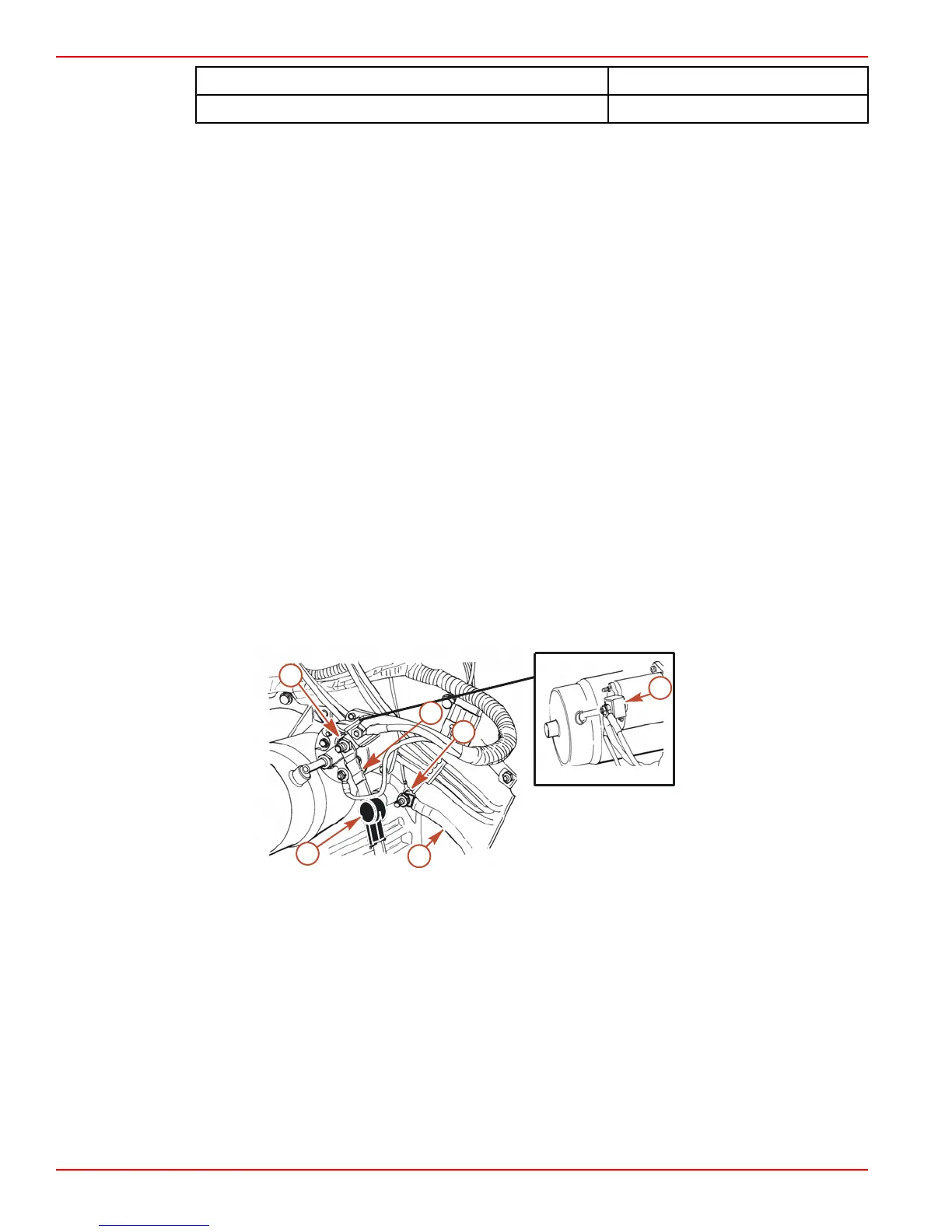
BATTERY CABLE TO ENGINE CONNECTIONS
d
a
c
f
b
e
15485
Typical inboard battery cable to engine connections
a - Negative (-) battery cable
(BLACK)
b - Ground stud (one each side of
flywheel housing)
c - Rubber boot (side over positive
terminal to prevent accidental
shorting)
d - Positive (+) battery cable (RED)
e - B+ starter terminal
f - 90-Amp fuse (DO NOT REMOVE)

 Loading...


