Cooling System
Page 7A-18 90-863758060 AUGUST 2006
Inboard V8 Water Flow Diagrams
Mie Water Flow Diagrams
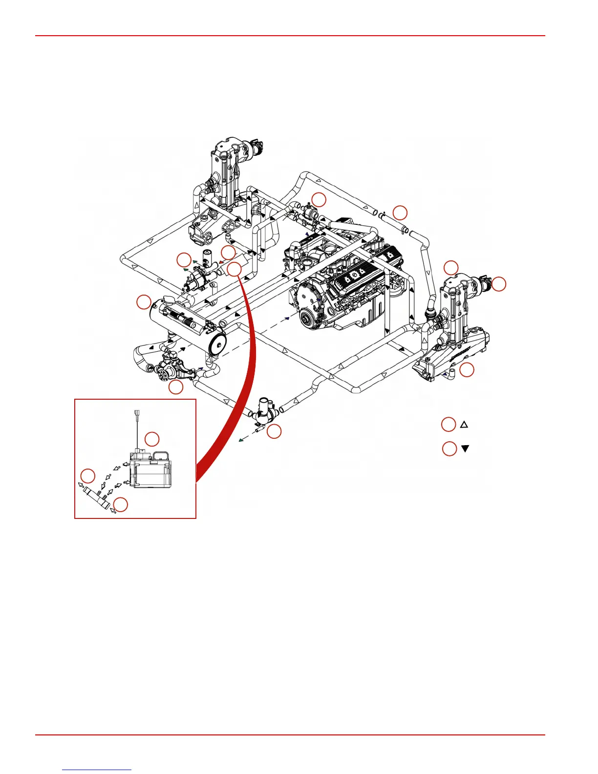
CLOSED COOLED INLINE EXHAUST MODELS
NOTE: Certain components in the following diagram may look different than on your
particular power package, but the water flow paths remain similar on all engines.
a
b
c
d
e
f
g
h
i
j
k
l
m
c
n
o
8182
a - Seawater inlet
b - Transmission cooler
c - Gen III Cool Fuel module
d - Exhaust and seawater outlet
e - Exhaust manifold
f - Distribution housing
g - Water circulating pump
h - Thermostat housing
i - 14 degree exhaust elbow
j - Seawater pump
k - Heat exchanger
l - To transmission cooler
m -From seawater pump
n - Seawater
o - Ethylene glycol mix

 Loading...


