Electrical System
90-863758060 AUGUST 2006 Page 8A-13
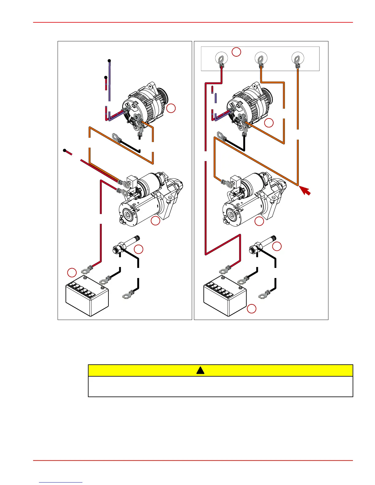
Battery Isolator Diagram
B2
A
B1
ORN
ORN
ORN
ORN
PPL
PPL
RED/PPL
RED
RED
BLK
BLK
BLK
BLK
BLK
RED/PPL
a
b
c
d
a
b
e
d
f
24376
RED
BLK
a - Alternator
b - Starter
c - Cranking battery
d - Ground stud
e - Auxiliary battery
f - Isolator
!
CAUTION
Avoid wiring damage. Do not cut the orange wire flush with the wiring loom. Doing so will
damage other wires in the loom.
1. Disconnect the orange wire from the alternator battery terminal. Splice sufficient gauge
wire to the orange wire and connect as shown.
2. The splice wire must be a minimum of 8 AWG.
3. Insulate and seal the end of the wire with liquid neoprene and heat shrink tubing.

 Loading...


