Fuel Delivery System
90-863758060 AUGUST 2006 Page 5A-3
The fuel tank is an integrated component of the boat. Refer to the special information on
service and maintenance, which you have received from the tank manufacturer.
Only a few points related to function and safety are listed here [Refer to boating standards
(NMMA, ABYC, etc.) and Coast Guard regulations for complete guidelines]:
• All connections should be on the upper side of the tank.
• The drain plug at the lowest point on the tank permits the removal of water and
sediment.
• The tank breather pipe must have an inner diameter of at least 13 mm (½ in.)and must
be fitted with a swan neck to prevent water from entering the tank.
It is recommended that the exact route and length of the fuel lines be established at the
first installation of the engine to prevent problems later in connecting them to the engine.
All fuel lines must be well secured. The holes where the lines run through the bulkheads
should be carefully rounded off or protected with rubber grommets. This prevents damage
to the lines from abrasion.
The following, but not limited to the following, additional fuel connection‑related points,
applying to all engines unless otherwise stated, must be considered [Refer to boating
standards (NMMA, ABYC, etc.) and Coast Guard regulations for complete guidelines]:
• The fuel pickup should be at least 25 mm (1 in.) from the bottom of fuel tank to prevent
picking up impurities.
• The maximum measured vacuum at the engine's fuel inlet must not exceed
6.9 kPa (1 psi) at 600, 3000, full throttle RPM, and idle RPM.
IMPORTANT: A vacuum reading higher than specified can cause vapor locking with some
fuels. It can also cause poor engine performance because of fuel starvation.
• Fuel lines used must be Coast Guard approved (USCG Type A1).
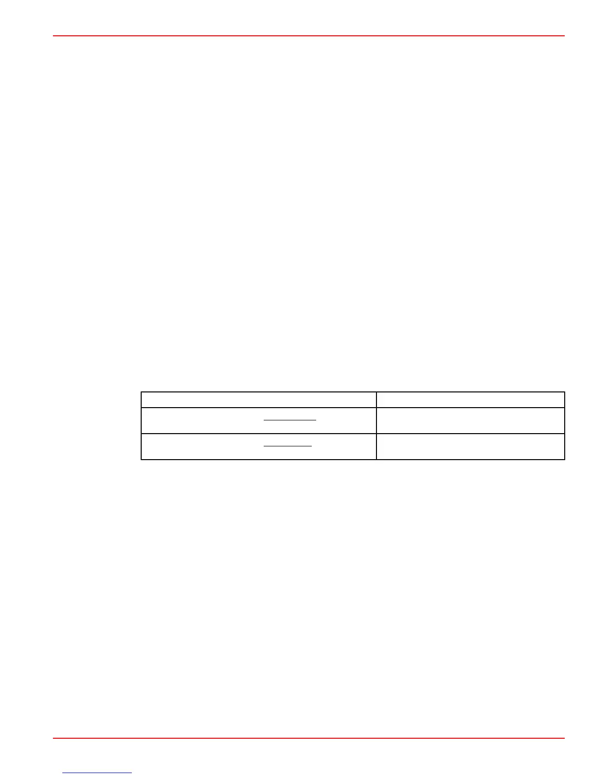
Description Specification
Minimum fuel line diameter on single‑engine gasoline
installations
10 mm (3/8 in.)
Minimum fuel line diameter on multi‑engine gasoline
installations
13 mm (½ in.) ID or larger
• On Multi-Engine Gasoline Installations, use a fuel pickup and fuel tank supply line
for each engine. If a single pickup and line is used, line must be 13 mm (½ in.) ID or
larger.
• Larger diameter (than previously specified) lines and fittings must be used on
installations requiring long lines or numerous fittings.
• Fuel lines should be installed free of stress and firmly secured to prevent vibration and/
or chafing.
• Sharp bends in fuel lines should be avoided.
• A flexible fuel line must be used to connect fuel supply line to fuel inlet fitting on engine
to absorb deflection when engine is running.
Fuel Tank
• The fuel tank must be properly vented to allow easy filling of the tank and prevent a
vacuum or pressure from being generated during normal operation. ABYC standards
recommend that the vent pipe and associated hardware be 11 mm (7/16 in.) ID
minimum.

 Loading...


