Instrumentation and Controls
90-863758060 AUGUST 2006 Page 9A-9
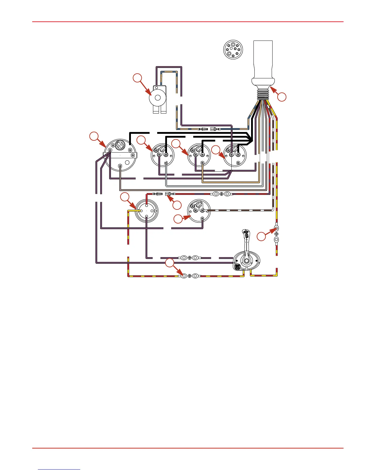
10-Pin Instrument Harness
SW
12V
LT
UNSW
GND
SIG
1
2
3
4
L
T
B
S
I
12V
SEND
GND
LT
12V
SEND
GND
LT
12V
SEND
GND
LTT
12V
SEND
GND
1
2
3
4
56
7
8
10
TAN/BLU
PPL
PPL
PPL
PPL
PPL
PPL
PPL
BLK
BLK
BLK
TAN
LT BLU
GRY
PPL
PPL PPL
YEL/RED
YEL/RED
7865
RED/PPL
BRN/WHT
YEL/RED
f
h
i
i
a
b
c
d
e
j
g
a - Audio warning buzzer
b - Tachometer
c - Oil pressure
d - Water temperature
e - Battery meter
f - Ignition switch
g - Trim indicator (Sterndrive only)
h - See Note 1 and Note 2
i - See Note 3
j - To engine wiring harness
Refer to gauge manufacturer's instructions for specific connections.
• Note 1: Connect wires together with screw and hex nut; apply liquid neoprene to
connection and slide rubber sleeve over connection.
• Note 2: Power for a fused accessory panel may be taken from this connection. load
must not exceed 40 amps. panel ground wire must be connected to instrument terminal
that has an 8-gauge black (ground) harness wire connected to it.
• Note 3: Lanyard stop switch lead and neutral safety switch leads must be soldered and
covered with shrink tube for a water proof connection. if an alternate method of
connection is made, verify connection is secure and sealed for a water proof
connection.

 Loading...


