Exhaust System
Page 6A-14 90-863758060 AUGUST 2006
• Install risers or lower the muffler if necessary to meet minimum exhaust elbow height.
• The water line inside the muffler is the beginning measurement point to determine the
correct elbow height.
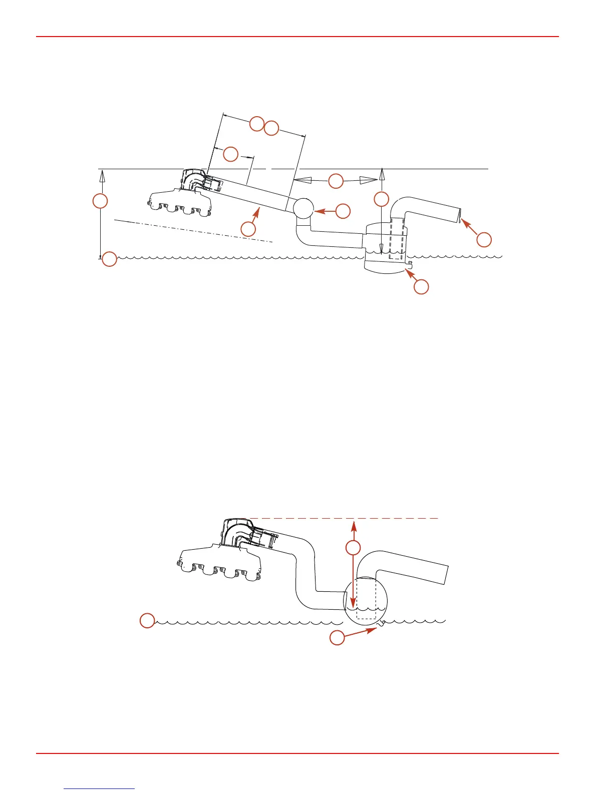
Collector and Water Lift Muffler
a
b
e
f
g
k
c
i
h
d
j
15636
Typical
a - Water line
b - Siphon break (vacuum valve) Must
be installed in cooling water circuit
if exhaust elbows are at or below
water level. Refer to muffler
manufacturing recommendations.
c - Exhaust back pressure check
point
d - Resonator
e - 46 cm (18 in.) minimum between
exhaust elbow and collector
f - 10° downward slope minimum
g - 3° downward slope minimum
h - Collector
i - Minimum exhaust elbow height with
maximum load
j - Drain fitting
k - External flappers
S‑pipe Used With Water Lift Muffler
a
c
b
7556
a - Water line
b - Minimum exhaust elbow height
with maximum load
c - Drain plug

 Loading...


