Cooling System
90-863758060 AUGUST 2006 Page 7A-21
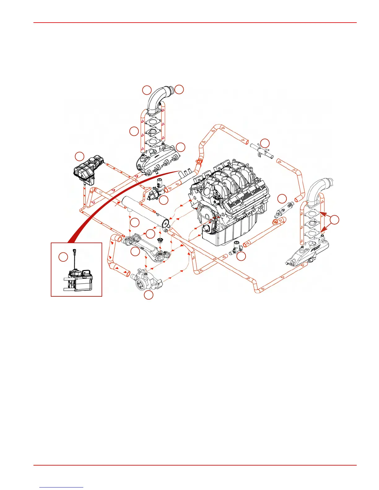
8.1S and HO Inboard Water Flow Diagram
Coolant and Water Flow Diagrams
NOTE: Certain components in the following diagram may look different than on your
particular power package, but the water and coolant flow paths remain similar on all
engines.
1
2
3
4
5
6
7
8
9
10
11
12
13
15
8227
14
1 - Seawater pump/Air actuator
2 - Air actuator
3 - Transmission cooler
4 - Oil cooler
5 - Gen III Cool Fuel Module
6 - Heat exchanger
7 - Thermostat
8 - Crossover
9 - Water circulating pump
10 - Coolant reservoir
11 - Exhaust manifold
12 - Elbow
13 - Water and exhaust outlet
14 - Gasket (2 per side)
15 - Turbulator (1 per side)

 Loading...


