Instrumentation and Controls
Page 9A-18 90-863758060 AUGUST 2006
• On Velvet Drive models, the shift lever must be in the designated detent position for
each gear.
e
b
a
d
c
7665
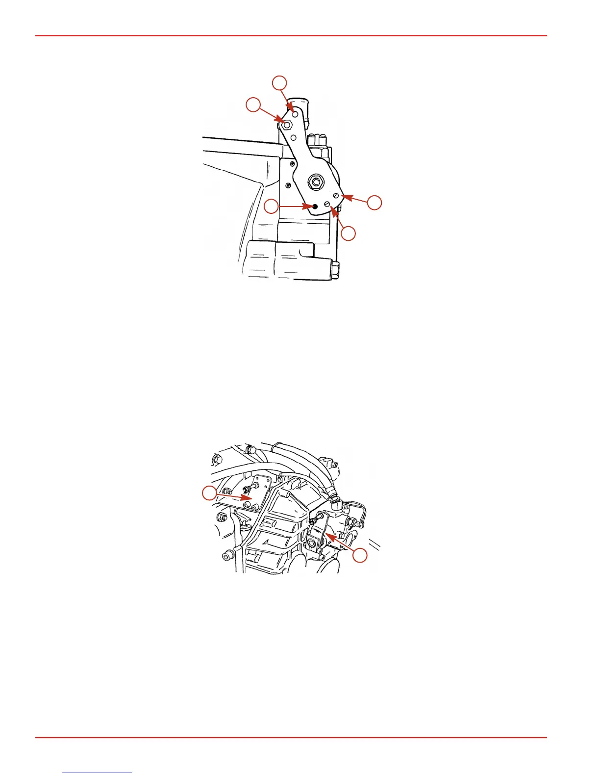
Velvet Drive 5000 series (8 degree down angle shown, V-drive similar)
a - Transmission shift lever
b - Poppet ball must be centered in
this detent hole when left-hand
propeller shaft rotation is desired
c - Poppet ball must be centered in
this detent hole when right-hand
propeller shaft rotation is desired
d - Poppet ball must be centered in this
detent hole for neutral position
e - Install shift lever stud in this hole
when using quicksilver shift cables
• On ZF Marine (Hurth) transmissions, the shift lever must be against the stops for
forward and reverse, and in the centered detent position for neutral.
8297
b
a
Typical ZF Marine (Hurth) transmission shown
a - Shift lever b - Shift cable bracket

 Loading...


