Engine
90-863758060 AUGUST 2006 Page 3A-19
• Check alignment by holding the flange and the coupler together and checking at 90°
intervals with a feeler gauge. The coupler should be rotated 180° and alignment
rechecked to ensure that the coupler and flange are in alignment.
a
c
b
7535
a - Propeller shaft coupler
b - Feeler gauge
c - Transmission output flange
Specification mm in.
Transmission output flange to propeller shaft coupler alignment
tolerance
0.0—0.07 0.0—0.003
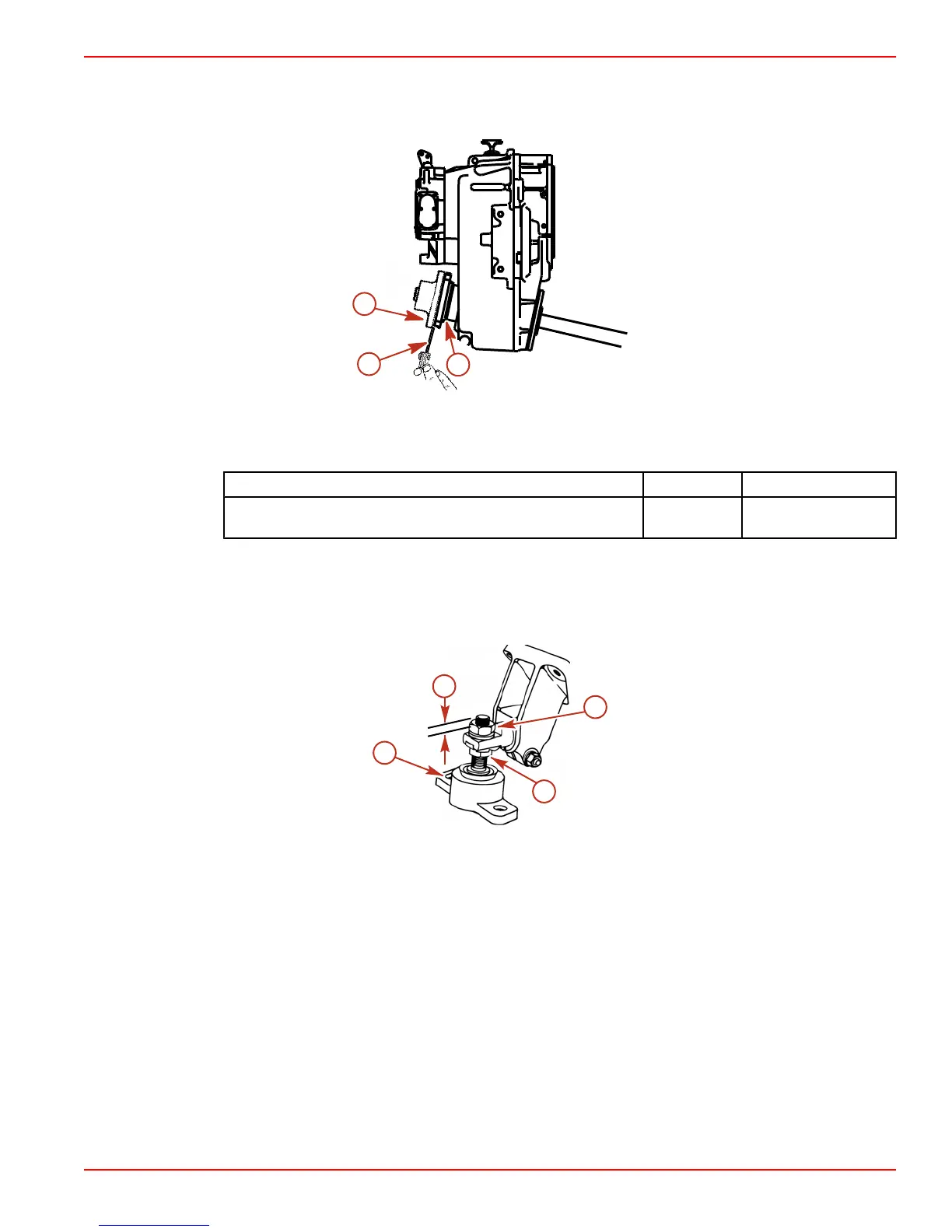
• The slot on the front mounts should face forward.
• The adjusting nuts on the port and starboard mounts should be adjusted evenly.
• A minimum of 6 mm (¼ in.) of up and down adjustment must exist on all four engine
mounts after final alignment to allow for realignment in the future.
a
d
b
c
7536
a - 6 mm (¼ in.) minimum adjustment
required for future alignment
b - Adjusting nut
c - Locknut
d - Slot

 Loading...


