Exhaust System
90-863758060 AUGUST 2006 Page 6A-9
a
d
e
f
h
c
g
i
b
15631
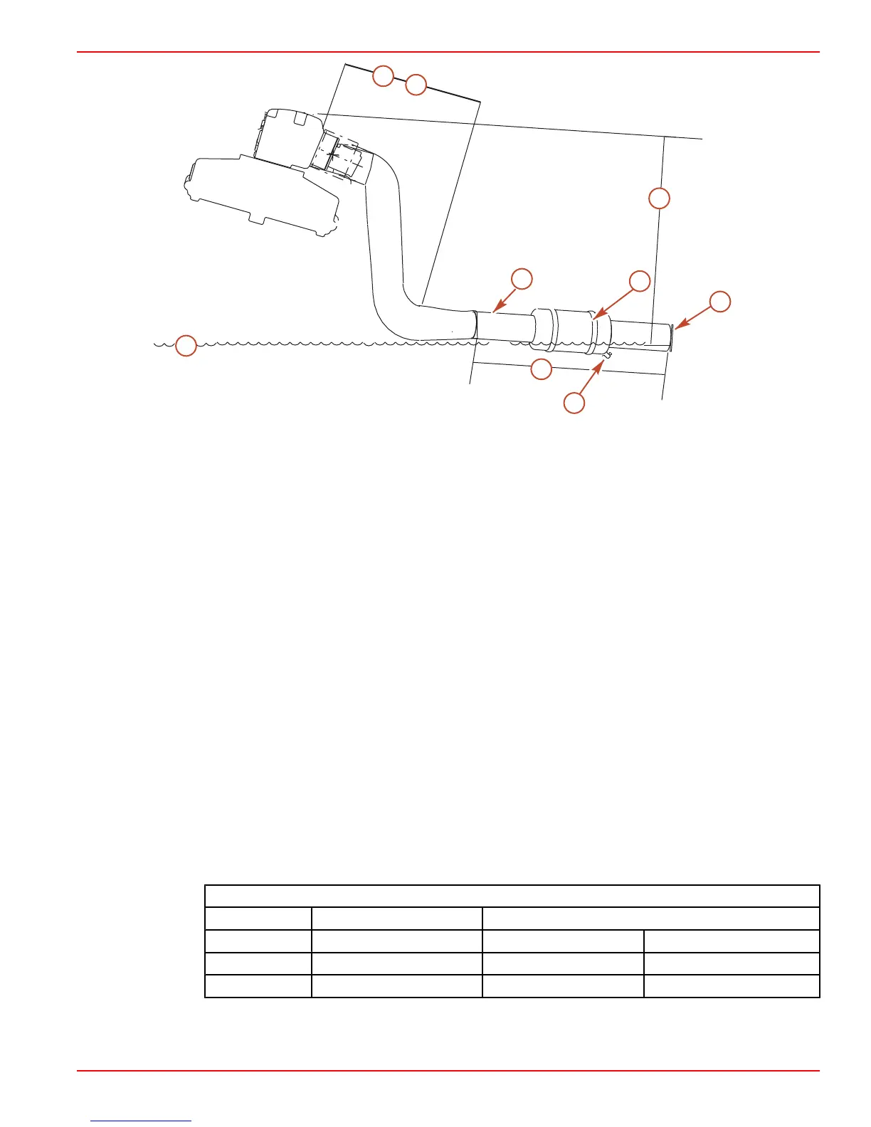
Typical single engine inboard with water standing in muffler (tow sports)
a - Water line
b - Minimum exhaust elbow height
with maximum load
c - Exhaust back pressure check
point
d - 46 cm (18 in.) minimum between
exhaust elbow and muffler
e - Minimum of 10° downward slope
in the first 46 cm (18 in.)
f - Muffler (must be self draining)
g - 3° downward slope minimum
h - External flappers
i - Drain fitting
• Applications with through‑transom fittings must be equipped with exhaust flappers to
prevent the reverse flow of water into the engine. (See Exhaust Through The Hull
Fittings).
• The muffler, collector, and exhaust hoses must be adequately supported for proper
orientation and to prevent overstressing the exhaust manifolds and elbows. The
support requirements will vary with exhaust system design and the amount of G‑forces
to be encountered.
• Exhaust resonators can be used on any models that may experience a water intrusion
problem associated with the tuning effects of the exhaust system. (See
Exhaust
Resonators
).
• Larger exhaust hoses should be used on applications with long hose runs.
Minimum Exhaust Hose Size
Model Dual Outlet System Single Outlet System
Dual Hose Portion Single Hose Portion
8.1S Models 102 mm (4 in.) 102 mm (4 in.) 127 mm (5 in.)
All others 76 mm (3 in.) 76 mm (3 in.) 102 mm (4 in.)
• A heat resistant exhaust hose that complies with specifications SAE J2006 or UL 1129
should be used (ABYC standard).

 Loading...


