32
|
VIKING 4G E, S
Rev. 1.0 (29.1.2020)
Installation
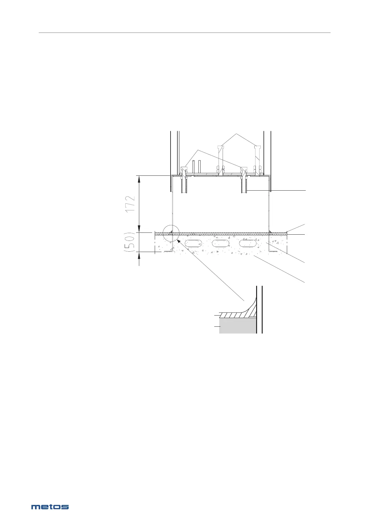
6.4.2. Subsurface frame cast into the fl oor
Installation frames are mounted according to the installation drawing, with the help of installation guides
supplied with the delivery. The frames must be installed in a horizontal position and fi xed so that they do
not move during casting. The installation frames must be positioned so that their upper surface is 172
mm above the fi nished fl oor surface. The junction of the installation frame and fl oor is fi lled with fl ooring
material. To achieve the best result regarding tightness, the installation frame should be fi lled up to the
top level with concrete mass which is covered with fl oor coating after the installation. Make sure that
the protective sleeves of the fi xing bolts are in place before fi lling the installation frame. The main points
concerning the installation of the subsurface frame are shown in the picture below.
1. Installation frame
2. Concrete casting
3. Finished fl oor surface
4. Floor coating
5. Fixing bolt
6. Protecting sleeve for fi xing bolt
7. Adjusting bolt
Place the kettle on the installation frame and adjust to a horizontal position with the adjusting bolts.
When the kettle is in a horizontal position, it must be fi xed to the installation frames with the help of the
fi xing bolts. The control pillar has 4 bolts and the support pillar has 2 bolts. Tighten the adjusting nuts
carefully. Do not seal the space between the kettle pillars and installation frame as there must be enough
change of air.
2
1
4
3
5
7
2
4
6