MI 3000 EasiPLUS Measurements
27
2. Press the TEST key in order to perform regular measurement. The
displayed result should be close to 0.00 .(depending on the length of test
leads used).
3. Press the CAL key. After performing test leads compensation the
compensated test leads indicator Co will be displayed on the top line.
4. In order to remove any test lead resistance compensation, follow the
procedure described in step3 with test leads separated from one another.
After removing any test lead compensation, the compensation indicator
will disappear from the top line of the display.
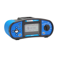
Step 4 Ensure that the item for testing is disconnected from any voltage source and it
has been fully discharged. Connect the test cables to the item under test.
Follow the connection diagrams shown in figures 5.6 and 5.7 to perform a
Low resistance measurement.
PCC1
PCC2
PCC3
N/L2
PE/L3
L/L1
MPEC
MPEC....Main Potential Equilizing Collector
PCC....Protection Conductor Collector
prolongation lead
Figure 5.6: Connection of universal test cable and optional probe test lead
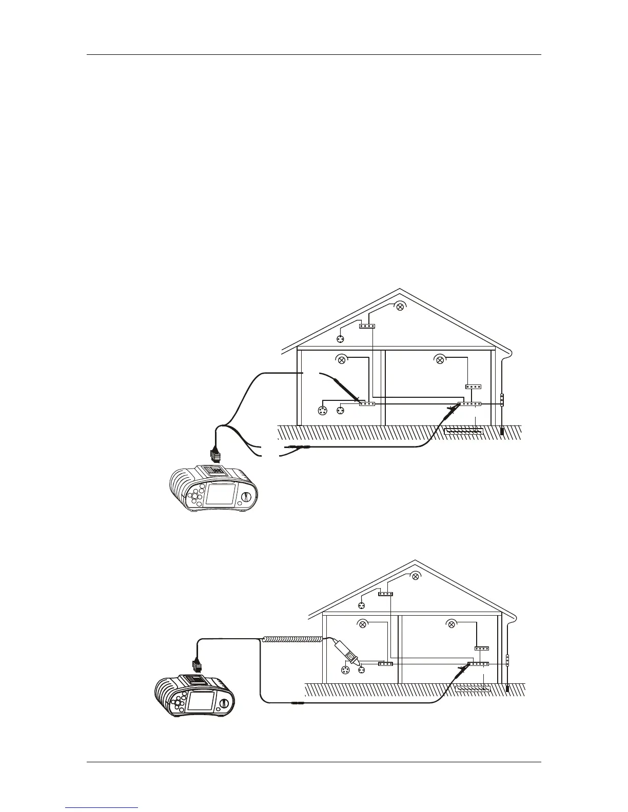
PCC1
PCC2
PCC3
MPEC
MPEC....Main Potential Equilizing Collector
PCC....Protection Conductor Collector
prolongation lead
Figure 5.7: Connection of tip commander and optional probe test lead
 Loading...