MI 3000 EasiPLUS Measurements
36
5.3.9 Autotest
The purpose of the autotest function is to perform a complete RCD testing and
measurement of most important associated parameters (contact voltage, fault loop
resistance and trip-out time at different fault currents) with one press of a button. If a
faulty parameter is noticed during the autotest, the test will stop to highlight the need for
further investigation.
Notes:
The measurement of contact voltage in the pre-test does not normally trip an RCD.
However, the trip limit may be exceeded as a result of leakage current flowing
through the PE protective conductor or a capacitive connection between L and PE
conductors.
The autotest sequence stops when the trip-out time is out of allowed time period.
5.3.9.1 How to perform RCD autotest
Step 1 Select RCD function with the function selector switch first. Use the / keys
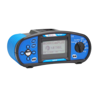
to select RCD autotest function (AUTO). The following menu is displayed:
Figure 5.21: RCD autotest menu
Step 2 Set the following measuring parameters:
Nominal differential trip-out current,
RCD type.
Step 3 Connect the test leads to the instrument and follow the connection diagram
shown in figure 5.15 (also see the chapter 5.3.6 Contact voltage) to perform
the RCD autotest.
Step 4 Check for any warnings and check the online voltage/terminal monitor
displayed on the screen before starting the measurement. If everything is ok,
press the TEST key. The autotest sequence will then start to run as follows:
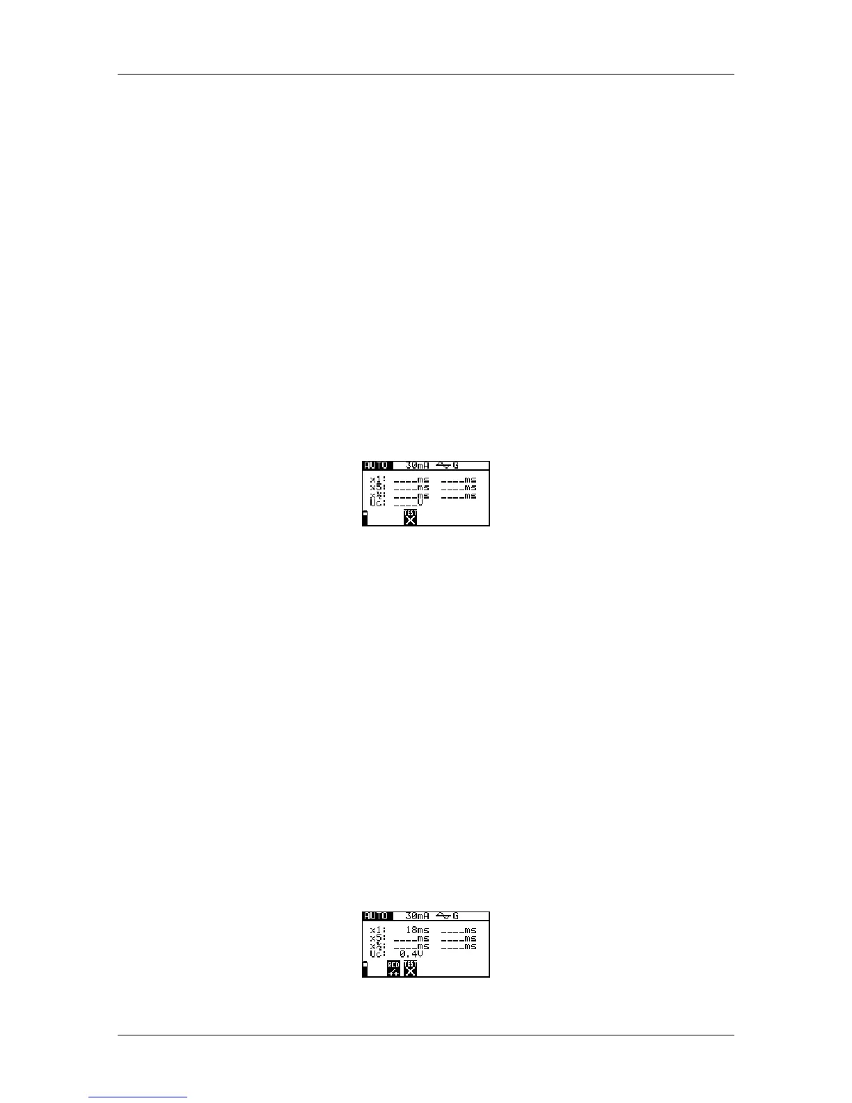
1. Trip-out time measurement with the following measurement parameters:
Test current of I
N
,
Test current started with the positive half-wave at 0
0
.
Measurement normally trips an RCD within allowed time period. The following
menu is displayed:
Figure 5.22: Step 1 RCD autotest results
 Loading...