MI 3000 EasiPLUS Measurements
34
Step 2 Set the following measuring parameters:
Nominal differential trip-out current,
Nominal differential trip-out current multiplier,
RCD type, and
Test current starting polarity.
Step 3 Connect the leads to the instrument and follow the connection diagram shown
in figure 5.15 (see the chapter 5.3.6 Contact voltage) to perform trip-out time
measurement.
Step 4 Check for any warnings and check the online voltage/terminal monitor on the
display before starting measurement. If everything is ok, press the TEST key.
After performing the measurement, results will appear on the display along
with a PASS/FAIL indication.
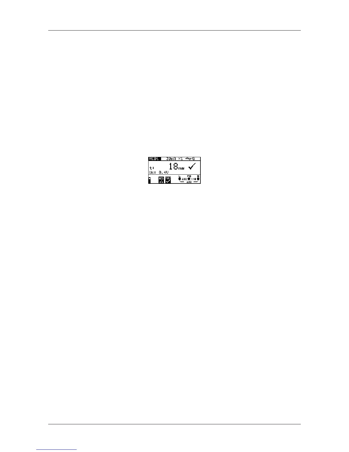
Figure 5.18: Example of trip-out time measurement results
Displayed results:
t ..............Trip-out time,
U
C
...........Contact voltage.
Notes:
Parameters set in this function are also transferred onto all other RCD functions!
RCD trip-out time measurement will be performed only if the contact voltage at
nominal differential current is lower than the limit set in the contact voltage
setting!
The measurement of the contact voltage in pre-test does not normally trip an
RCD. However, the trip limit may be exceeded as a result of leakage current
flowing through the PE protective conductor or a capacitive connection between
L and PE conductors.
5.3.8 Trip-out current
This test is used to determine the minimum current required to trip the RCD. After the
measurement has been started, the test current generated by the instrument is
continuously increased, starting at 0.2I
N
to 1.1I
N
(to 1.5I
N
/ 2.2I
N
(I
N
=10 mA)
for pulsating DC residual currents), until the RCD trips.
For additional information concerning the trip-out current measurement, refer to Metrel’s
handbook Measurements on electric installations in theory and practice.
 Loading...