MI 3000 EasiPLUS Measurements
29
Step 2 Set the following limit value:
High limit resistance value.
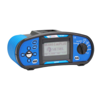
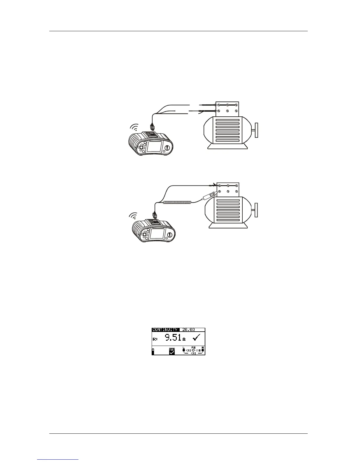
Step 3 Connect test cable to the instrument and the item under test. Follow the
connection diagram shown in figures 5.10 and 5.11 to perform the Continuity
measurement.
Ry
S
z
T
x
N
/
L
2
P
E
/
L
3
L
/
L
1
Figure 5.10: Connection of universal test cable
Ry
S
z
T
x
Figure 5.11: Connection of tip commander
Step 4 Check the warnings and online voltage/terminal monitor on the display before
starting the measurement. If everything is OK, press the TEST key to start the
measurement. The actual measuring result with PASS/FAIL indication (if
applicable) will be displayed during the measurement.
As this is a continuous test, the function will require stopping. To stop the
measurement at any time press the TEST key again. The last measured
result will be displayed together with the PASS/FAIL indication (if applicable).
Figure 5.12: Example of Low current continuity measurement result
Displayed result:
R.............Low current continuity resistance result.
Warning:
Low current continuity measurement should only be performed on de-energized
objects!
 Loading...