MI 3000 EasiPLUS Measurements
40
The complete list of available fuse types can be found in Appendix A.
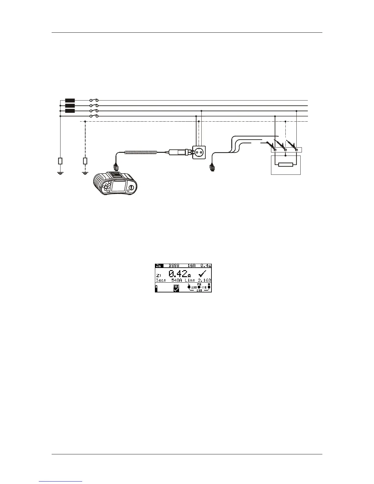
Step 3 Connect the test leads to the instrument and follow the connection diagram
shown in the figure 5.29 to perform fault loop impedance measurement.
L1
L2
L3
N
PE
R
E
Ro
LPEN
L
/
L
1
N
/
L
2
P
E
/
L
3
Figure 5.29: Connection of plug cable and universal test cable
Step 3 Check for any warnings displayed on the screen and check the online
voltage/terminal monitor before starting the measurement. If everything is ok,
press the TEST key. After performing the measurement, the test results will
appear on the display together with the PASS/FAIL indication (if applicable).
Figure 5.30: Example of loop impedance measurement results
Displayed results:
Z .............Fault loop impedance,
I
SC
...........Prospective fault current (displayed in amps),
Lim .........High limit fault loop impedance value (if applicable).
Notes:
The fault loop impedance limit depends on the fuse type, fuse current rating, fuse
trip-out time and Impedance scaling factor.
The specified accuracy of test parameters is valid only if mains voltage is stable
during the measurement.
The Fault loop impedance measurement trips RCD protected circuits.
 Loading...