MI 3000 EasiPLUS Measurements
L1
L2
L3
N
PE
R
E
Ro
LPEN
L
/
L
1
N
/
L
2
P
E
/
L
3
N/L2
L
/
L
1
PE/L3
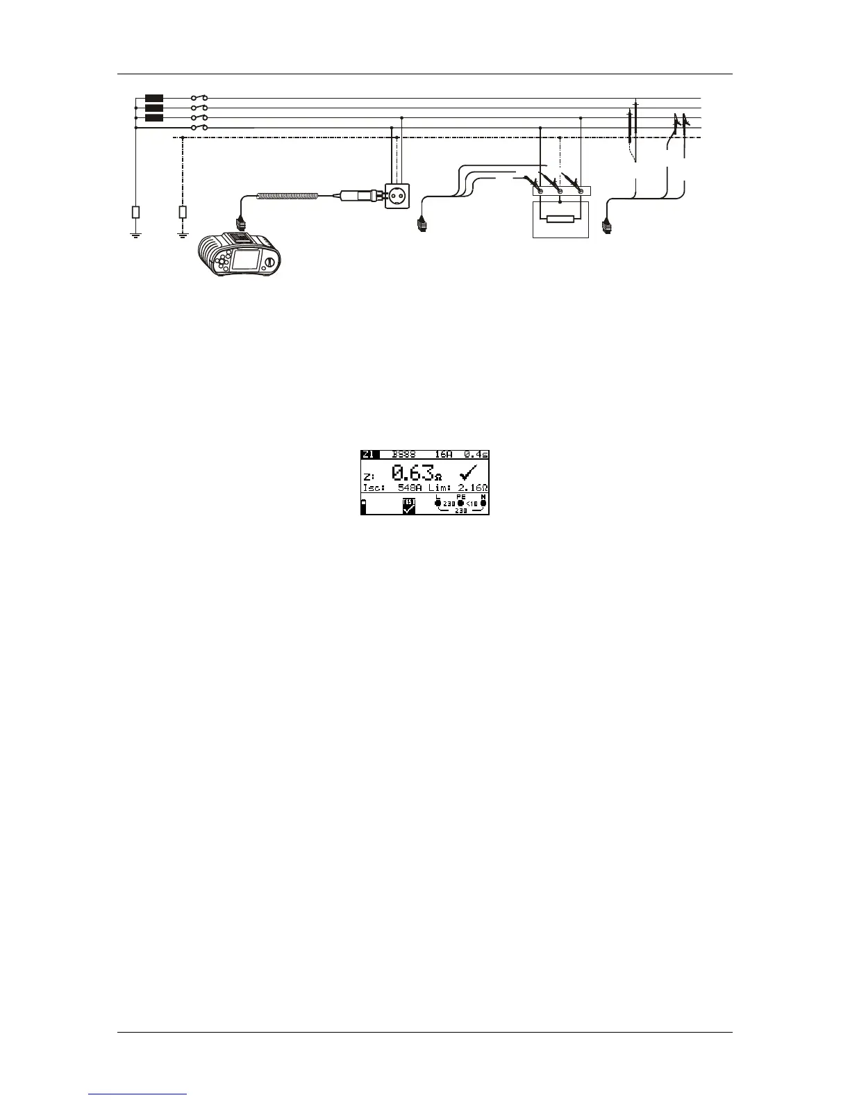
Figure 5.34: Phase-neutral or phase-phase line impedance measurement
Step 4 Check for warnings displayed on the screen and check the online
voltage/terminal monitor before starting the measurement. If everything is ok,
press the TEST key. After performing the measurement, the results will
appear on the display together with the PASS/FAIL indication (if applicable).
Figure 5.35: Example of line impedance measurement results
Displayed results:
Z .............Line impedance,
I
SC
...........Prospective short-circuit current,
Lim .........High limit fault loop impedance value (if applicable).
Notes:
The fault loop impedance limit depends on fuse type, fuse current rating, fuse
trip-out time and Impedance scaling factor.
The specified accuracy of the test parameter is valid only if mains voltage is
stable during the measurement.
44
 Loading...