MI 3000 EasiPLUS IT supply systems
63
Line resistance
Line resistance Resistance R
L1-L2
.
Prospective short circuit
current
I
PSC
for U
L1-L2
= 110 V.
Fault loop resistance
Fault loop resistance Both fault loops, R
1
(L1-PE) and R
2
(L2-PE).
Prospective fault current I
SC1
and I
SC2
for both fault loops.
Voltage, frequency
Symbols modified for reduced low voltage system.
Phase rotation
Three-phase system automatic detected.
RCD functions
Contact voltage U
C
For both posibilities, U
1
(L1-PE) and U
2
(L2-PE).
Trip-out time
Trip-out current
Automatic test
Maximum nominal differential current limited to 1 A.
PE test probe
Disabled.
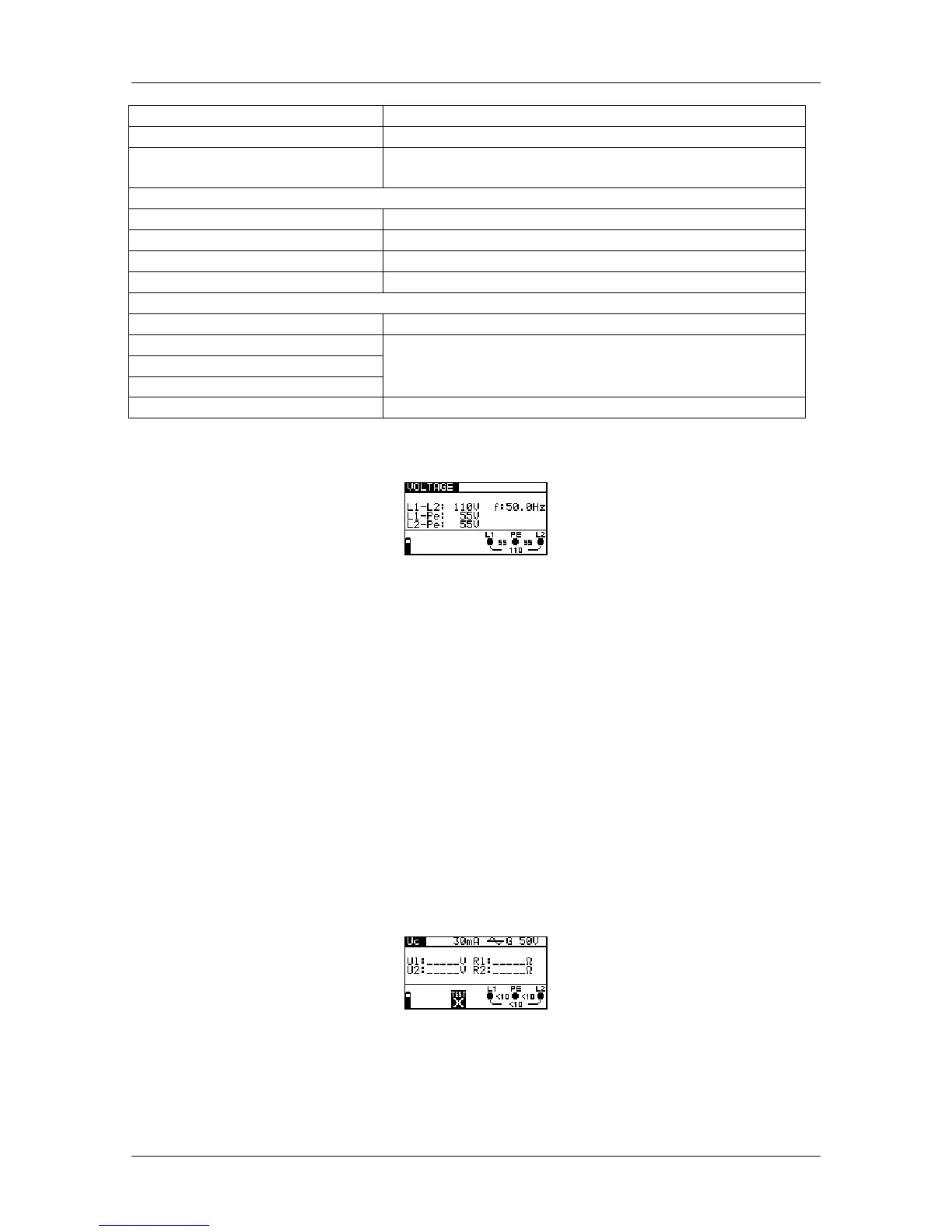
C.3.1 Voltage
Figure C.2: Example of voltage and frequency measurements
Displayed results for single phase system:
L1-L2 ......Voltage between line conductors,
L1-pe ......Voltage between line 1 and protective conductors,
L2-pe ......Voltage between line 2 and protective conductors.
C.3.2 RCD testing
Maximum regular RCD test current is 1 A r.m.s. (1.4 A peak) and can be achieved only
when fault loop resistance is lower than 1
Tests are carried out for both combinations (L1-PE and L2-PE) automatically.
Each individual test result is accompanied with appropriate indication.
Figure C.3: RCD contact voltage test
 Loading...