123
• Red LED is lit above the OUTPUT terminal to indicate that the output signal is connected to output
terminals. The display shows the symbol of connected output terminals.
Note
• Load of output terminals is limited similarly to corresponding voltage or current ranges.
• Output signals provided at Hi - Lo terminals and AUXILIARY connector are short-circuit proof.
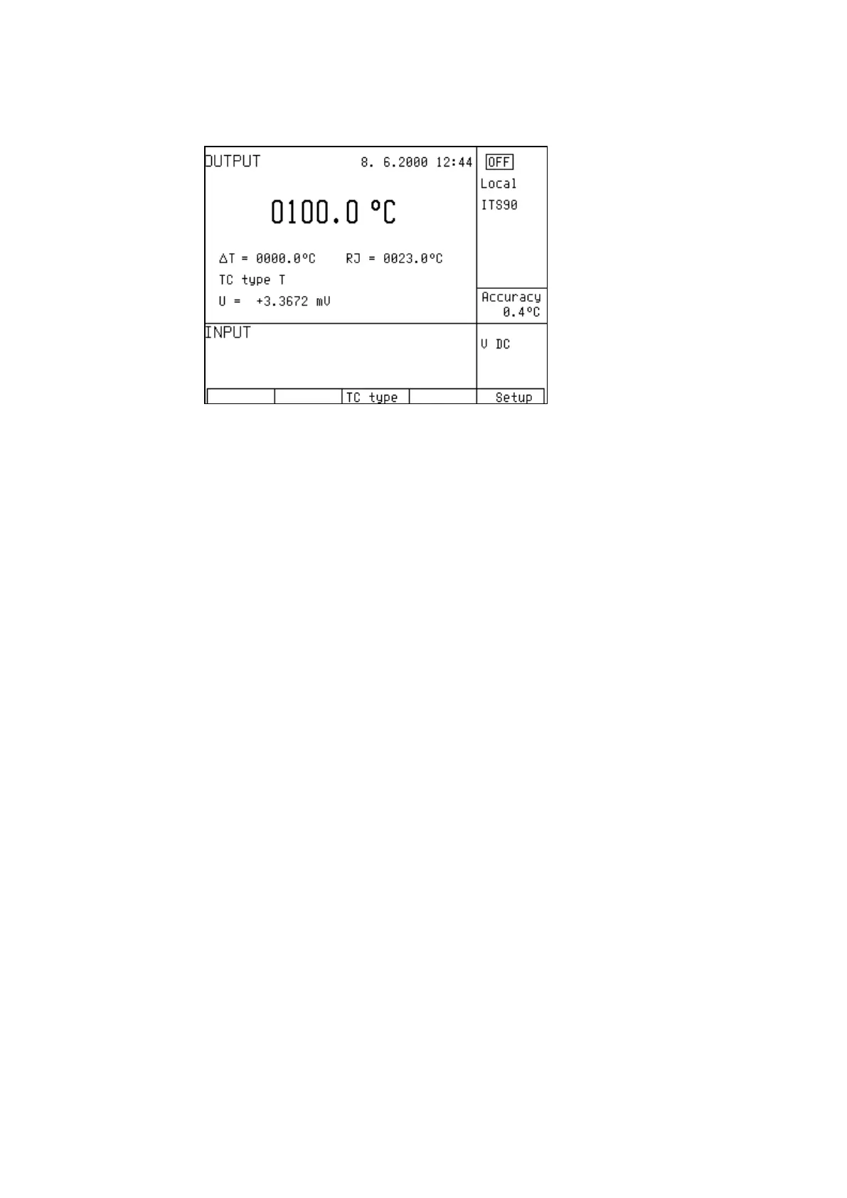
18.15.3. Switching between temperature sensor types
• Keep pressing “TC type” or “RTD type” display button to select desired sensor type.
• If resistance temperature sensors are selected, each press of the button selects Pt1.385, Pt1.392 or Ni
resistance thermometer. The display shows current setting as Pt385 / Pt392 / Ni.
• If thermocouples are selected, each press of the button selects K, N, R, S, B, J, T, E types. The display
shows current setting as TC TYPE x, where x is the type of the thermocouple.
18.15.4. Entry of R0 coefficient for resistance temperature sensors
For resistance temperature sensors, resistance at 0
o
C labeled R0 can be set. The range is 20 Ω to 2kΩ for
all types of resistance temperature sensors.
• Select the resistance temperature sensor mode and keep pressing the center cursor button
until [ _ _ _ _ _ _ _ ] symbols appear under the R0 coefficient value (R0 = xxxx Ω).
• Set the value using numeric keyboard and confirm by pressing “ Ω” or “kΩ ” display button or
by pressing ENTER.
 Loading...