159
Connection of the frequency output
The calibrator can be used for basic calibration of oscilloscopes. The calibrator provides the following functions.
• check of time base up to 20 MHz using squarewave signal. The function is activated by pressing F direct
mode button and selecting HF mode. Frequency can be set.
• check of vertical channel input sensitivity from 1 mV to 10 V in the frequency range up to 10 kHz. The
function is activated by pressing F direct mode button and selecting PWM mode. Frequency, amplitude
and duty cycle can be set.
• check of bandwidth using a signal up to 20 MHz with very steep rising edge (less than 5 ns). Calibration
of time period using squarewave signal whose period can be set up to 10 s, with selectable duty cycle.
The function is activated by pressing F direct mode button and selecting PWM mode. Frequency can be
set. The delay of the signal displayed on the oscilloscope’s screen is checked.
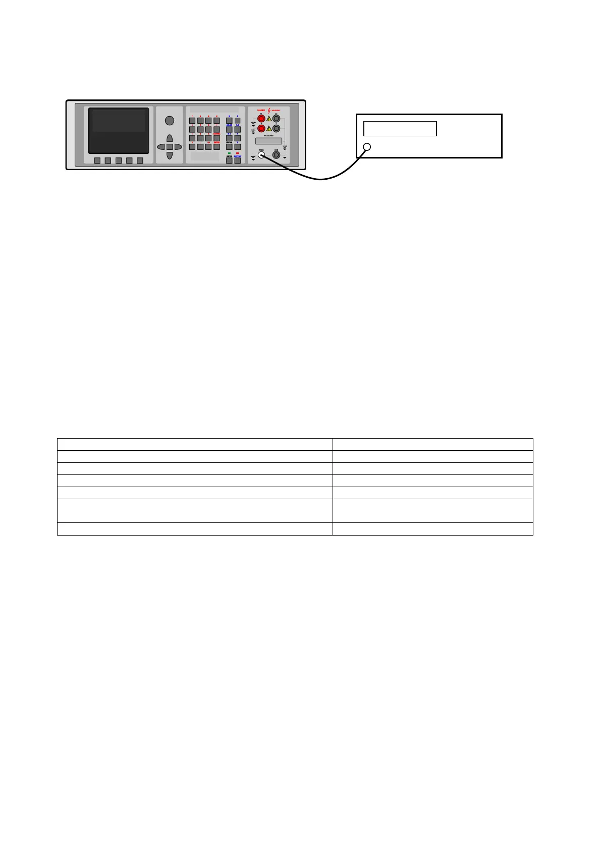
The oscilloscope to be calibrated connects to FREQ connector using a coaxial cable.
26.2. Measurement
Thanks to built-in multimeter, the calibrator can be used for basic calibration of some sources of electrical
signals. The table lists the type of adapter which is necessary for a particular measurement.
Applications and desired options
Impulse frequency to 15 kHz
Temperature through external TC sensor
Temperature through external RTD sensor
Non-electric quantities with strain gauge sensors (force,
pressure, torque, etc.)
26.2.1. Voltage, current and frequency
10 V voltage range, 20 mA current range and frequency up to 15 kHz can be measured using Opt. 40 cable.
The connection simple. The cable is connected to calibrator’s AUXILIARY connector, the other end has
bananas which connect calibrator to the measured object. When making the connection, observe the polarity
and connect the calibrator’s L terminal to the L (common) or grounded terminal of the measurement instrument.
To activate the measurement, select the respective function mode and press INPUT to measure the input
value.
 Loading...