160
ATTENTION
The input terminals of the built-in multimeter are floating. Maximum voltage between
the input terminals and the chassis is 15 Vpk. If this value is exceeded, the
multimeter can be damaged.
If the measurement range is exceeded, the calibrator displays an error message; input terminals are
disconnected only in the voltage and current measurement mode and remain connected in all other modes.
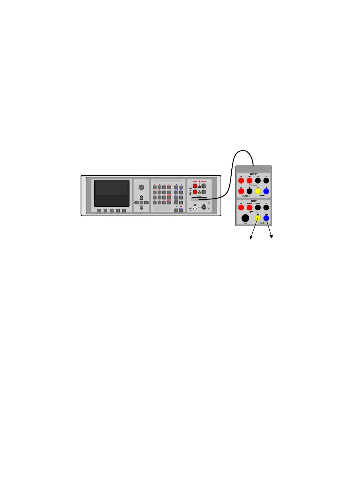
If 140-41 cable adapter is used, the signal to be measured is connected to U/I – COM terminals. COM is the
common terminal of the multimeter.
Connection of the multimeter when measuring the voltage, current and frequency using Opt. 140-41 cable
adapter
The multimeter allows the measurement of small DC voltages in the range of 0 to 2 V. 140-41 cable adapter
is required. The signal to be measured connects to Hu/+mV and Lu/-mV terminals. Lu/-mV is the common
terminal of the multimeter. To activate the measurement, select mVDC function mode using METER button in
the function menu and press INPUT to measure the input value.
26.2.2. Measurement of resistance or temperature using resistance temperature
sensors
Resistance can only be measured using four-wire connection using Opt. 60. Opt. 60 cable ends with four
bananas, labeled Hi, Hu, Lu, Li. Their meaning is as follows:
• Hi current terminal H
• Hu voltage terminal H
• Lu voltage terminal L
• Li current terminal L
During the measurement of resistance or temperature using resistance temperature sensors, the rules
applicable to the four-wire connection must be observed.

 Loading...