150
25. SYSTEM CONTROL
The calibrator includes standardized IEEE-488 bus and RS232 serial line. System connectors are located at
the rear panel. For the remote control to work properly, bus parameters must be set in the system menu. For
IEEE-488 bus, address is important (0 to 30 setting range). For RS232 bus, communication speed can be set
(150 to 19200 Bd) and software handshake XON/XOFF can be set. The calibrator can be only controlled by
one interface at a time. It is therefore necessary to select one of the interfaces (GPIB/RS232) using the system
menu.
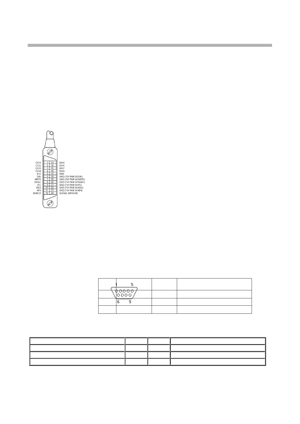
25.1. IEEE-488 bus properties
The instrument performs the following functions based on GPIB bus commands:
SH1, AH1, T5, L3, RL1, DC1, SR1
The instrument also recognizes the following general commands:
DCL Device Clear
SDC Selected Device Clear
EOI End or Identify Message Terminator
GTL Go To Local
LLO Local Lock Out
SPD Serial Poll Disable
SPE Serial Poll Enable
25.2. R S 232 bus properties
To transfer the data using RS232 bus, 8N1 data format is used, i.e. each data word includes 8 bits, no parity
and one stop bit. The communication speed can be set using the system menu. Available values: 150, 300,
600, 1200, 2400, 4800, 9600 and 19200 Bd. Software handshake (communication control) XON/XOFF can be
set to control the transfer of the data through the bus.
RS-232 connector layout
9-pin connector D-SUB MALE
Cable between the calibrator and PC (configuration 1:1)

 Loading...