3.6 Parameters, key <PARAM>
756/831 KF Coulometer, Instructions for Use
32
3.6.2 Control parameters and Ipol
The standard control parameters are optimal for most applications and should not be
altered. If you nevertheless need to alter the control parameters for special reagents
and/or samples take care that the polarization current of the indicator electrode, the
endpoint and the control range are linked to each other.
0
50
100
150
200
250
300
350
0 200 400 600 800 1000 1200 1400 1600
W a sse r / u g
Messwert / mV
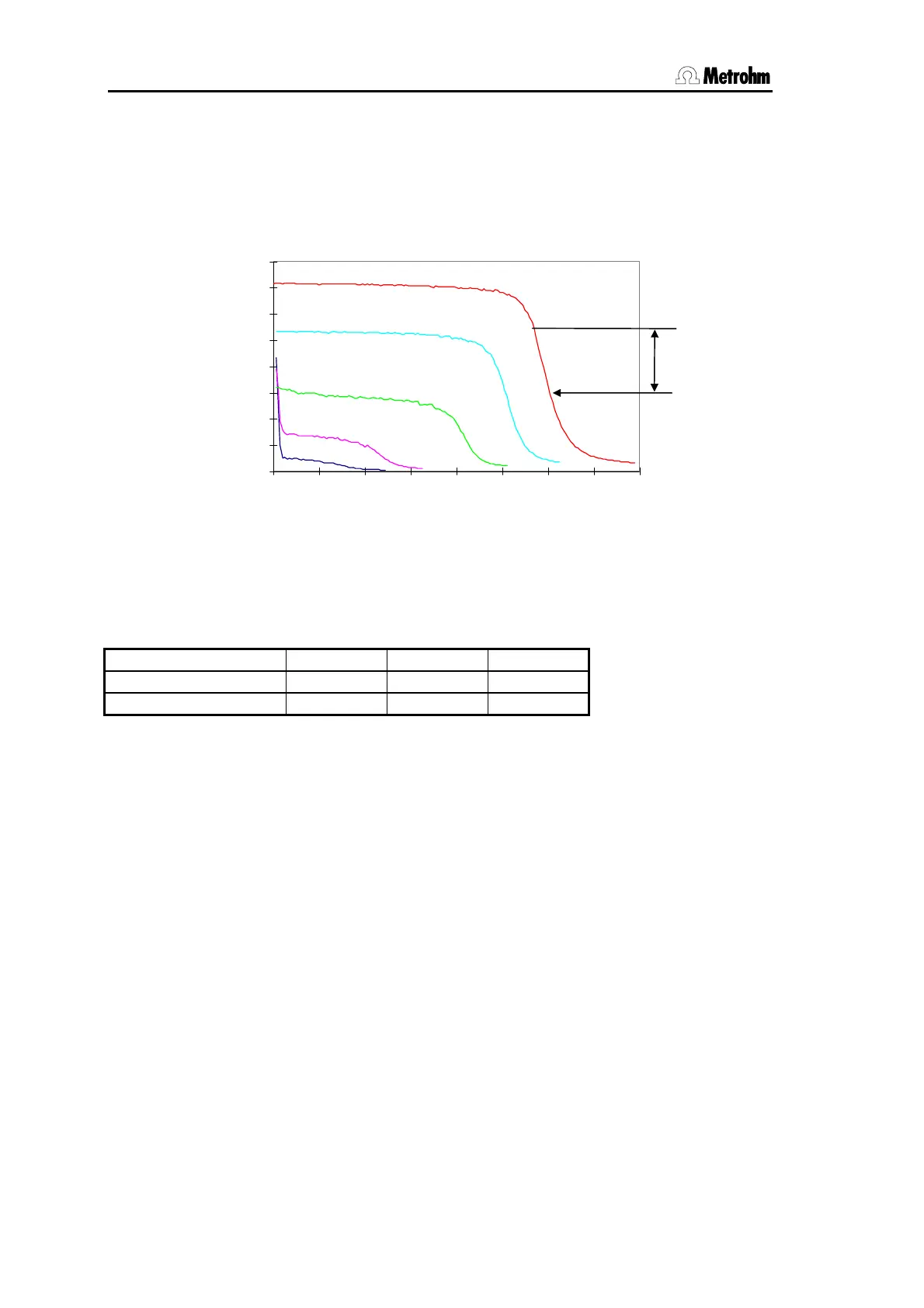
The diagram shows KF titration curves at different polarization currents (reagent Coulomat
AD). It is clear to see that the position of the endpoint varies with the polarization current.
The curves have different slopes, i.e. dynamics must also be adapted. Polarization
currents smaller than 10 uA are not suitable for this application. The following table gives
an idea of the optimal control parameters for various polarization currents.
Ipol 10 uA 20 uA 30 uA
EP 50 mV 100 mV 150 mV
dynamics 70 mV 100 mV 120 mV
min.rate, max.rate and stop drift = standard values.
After a certain period of use in the same reagent the indicator electrode will become
activated, i.e. the titration curve becomes steeper. If the titration curve is too steep then
slowly varying drift values may occur during conditioning. Remedied by: setting lower EP.
EP values which have been set too low can lengthen the titration time and therefore have
an unfavorable influence on the measuring error.
3.6.3 Drift
Secondary reactions and the penetration of atmospheric moisture mean that a certain
amount of iodine is always consumed during conditioning. This consumption is known as
the drift. Drift is shown in the Coulometer display in ug H
2
O per minute.
Drift is used for the start and stop criterion, as well as for the drift correction of the result:
I
pol
= 30 uA
I
pol
= 20 uA
I
pol
= 10 uA
I
pol
= 5 uA
I
pol
= 2 uA
I
pol
= 30 uA
I
pol
= 20 uA
I
pol
= 10 uA
I
pol
= 5 uA
I
pol
= 2 uA
EP
dynamics
Water / ug
Measured value / mV