2 BAR 70 en 17
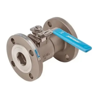
3. Open the on/off disc by rotating the drive shaft 180° coun-
terclockwise, so as to expose the sealing element (see
Figure 20 valve swiveled by 180°). Secure the on/off disc,
for example using wooden wedges to exclude pinch point
or crushing hazard. Pay attention to the fact that the seal-
ing surface of the on/off disc is not damaged as a result.
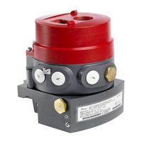
Figure 18 Valve in 0° position
Figure 19 Valve swiveled by 180°
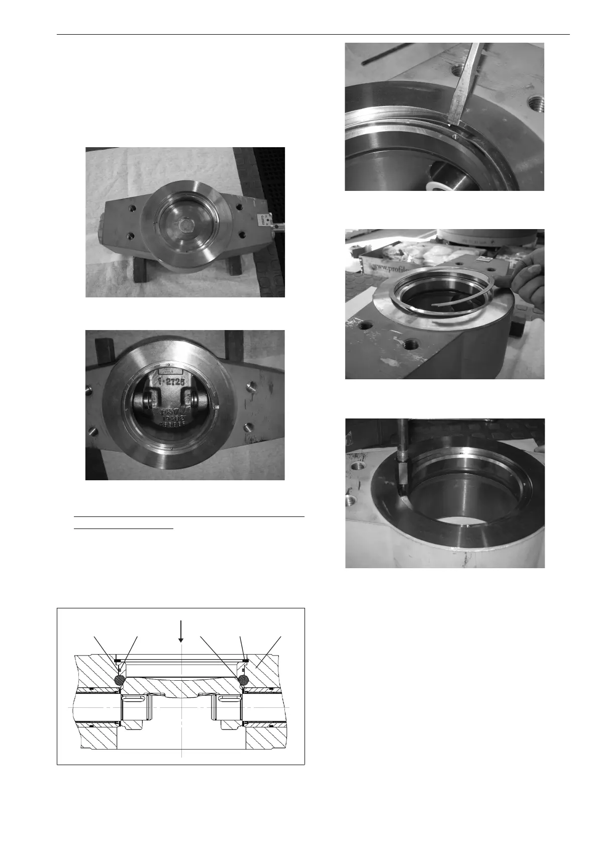
4. For valve size 3"-12”/DN80-300 in class Cl300/PN40 and
3”/80DN in Cl 600/PN63
Dismantle the spiral-shaped retaining ring (310) (see
figure 21 - figure 23). The sealing ring (301) is now
detached and can be removed (see Figure 23)by means
of an extraction tool. There are two detaching threads
in the sealing ring for this purpose.
Figure 20 Dismantling the retaining ring
Figure 21 Dismantling the retaining ring
Figure 22 Dismantling the retaining ring
Figure 23 Dismantling the sealing ring
Information:
For the following valve sizes, a retaining ring with clamp
type socket (see Figure 24) is used instead of the spiral
retaining ring:
□ 16“/ DN400, 20“/DN500 in class Cl300/PN40
□ all sizes in Cl600/PN63, except 3”/DN80
Carefully unscrew screw (313) because this is secured with
Loctite.
Remove the tab washer (312) and the clamp type socket
(311).
Dismantle the retaining ring (310). The sealing ring (301) is
now detached and can be removed by means of an extrac-
tion tool (see Figure 22).
There are two detaching threads in the sealing ring for this
purpose.
301
 Loading...