16 2 BAR 70 en
If you do not make the disassembly by yourself, instruct the
qualified personnel and provide them with protective
clothing, if necessary.
While assembling and disassembling the on/off (butterfly)
valve, the on/off (butterfly) valve must be closed to exclude
any incidental damage.
10.4 Disassembly
Ensure that:
□ The pipeline is pressureless and cleaned well.
□ The relevant valve is disengaged from the process.
□ The valve is in a defined position – “closed” in general.
Caution – Danger of explosion! It is mandatory to follow
the safety instructions of the operator!
Proceed in the following sequence for dismantling the
on/ off (butterfly) valve:
□ Close the on/off (butterfly) valve.
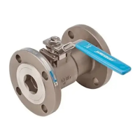
□ If the actuator must be removed for dismantling the on/
off (butterfly) valve, mark its direction to the bracket and
the body with a waterproof felt-tip pen before disman-
tling the actuator. (see Figure 16). In this manner you
can correctly reposition the drive during reinstallation
and prevent it from triggering any faulty function.
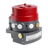
Figure 15 Securing using lifting ropes
Figure 16 Marking of the actuator position
Dismantle the actuator. Refer to point 4.5 of the IMO for this
□ Secure the on/off (butterfly) valve using lifting ropes. Do
not bring the lifting ropes close to the body (and the
shaft) of the on/off (butterfly) valve. (see Figure 15).
□ Release the on/off (butterfly) valve by loosening the
screws opposite to one another or the nuts in a cross-
wise manner.
□ Transport the on/off (butterfly) valve securely, so that
they do not move during transport and eventually get
damaged.
10.5 Reassembly
Proceed as follows for reassembling the on/off (butterfly)
valve:
□ Close the on/off (butterfly) valve.
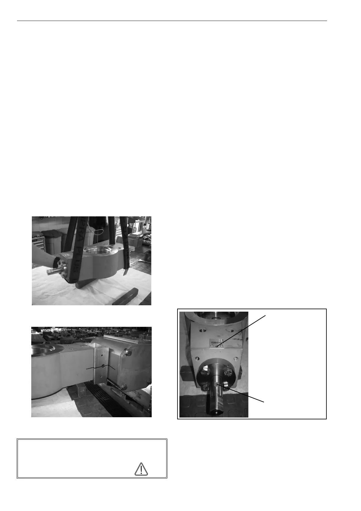
□ A round marking is at the end of the drive shaft and on
the body of the on/off (butterfly) valve respectively. The
round marking on the drive shaft should point in the
direction of the round marking on the body during rein-
stallation (see figure 17).
□ Bring the actuator to the “closed” position.
□ Ensure that you set the actuator in the correct position
on the drive shaft. Use the marking that you made on
the bracket and the actuator while dismantling the on/
off (butterfly) valve, and pay attention to most accurate
alignment of the marking on all components (body–
bridge – drive) See figure 16 Marking of the actuator
position.
□ Install the on/off (butterfly) valve between the pipelines
(see chapter 4.3 and following)
10.6 Replacement of the sealing element
If you want to change the sealing element at the high-per-
formance valve, then please proceed as follows (see
Figure 17):
Figure 17 Replacing the sealing element
1. Dismantle the valve in 0°-position (closed) (see
figure 18). Instructions for disassembly can be found
from chapter 4.5 of the IMO.
2. Fix the valve in a slip and tilt-proof manner on a stable
base or workbench.
Disconnect the energy supply to the actuator. In
addition, press the EMERGENCY STOP switch for
energy supply to the actuator or activate the remote
control, so that no one can reconnect
the energy supply by mistake.
Marking on the body
Marking on the drive shaft
 Loading...