2 BAR 70 en 9
4 Detaching and mounting the actuator
of type F1A/F1F
4.1 General
4.2 Mounting preparation
Lifting gear is required for installing larger actuators in situ.
The actuator type and size are indicated on the identifica-
tion plate (Figure 9 Identification plate of the actautor).
The weight of the actuator is specified in the following
table.
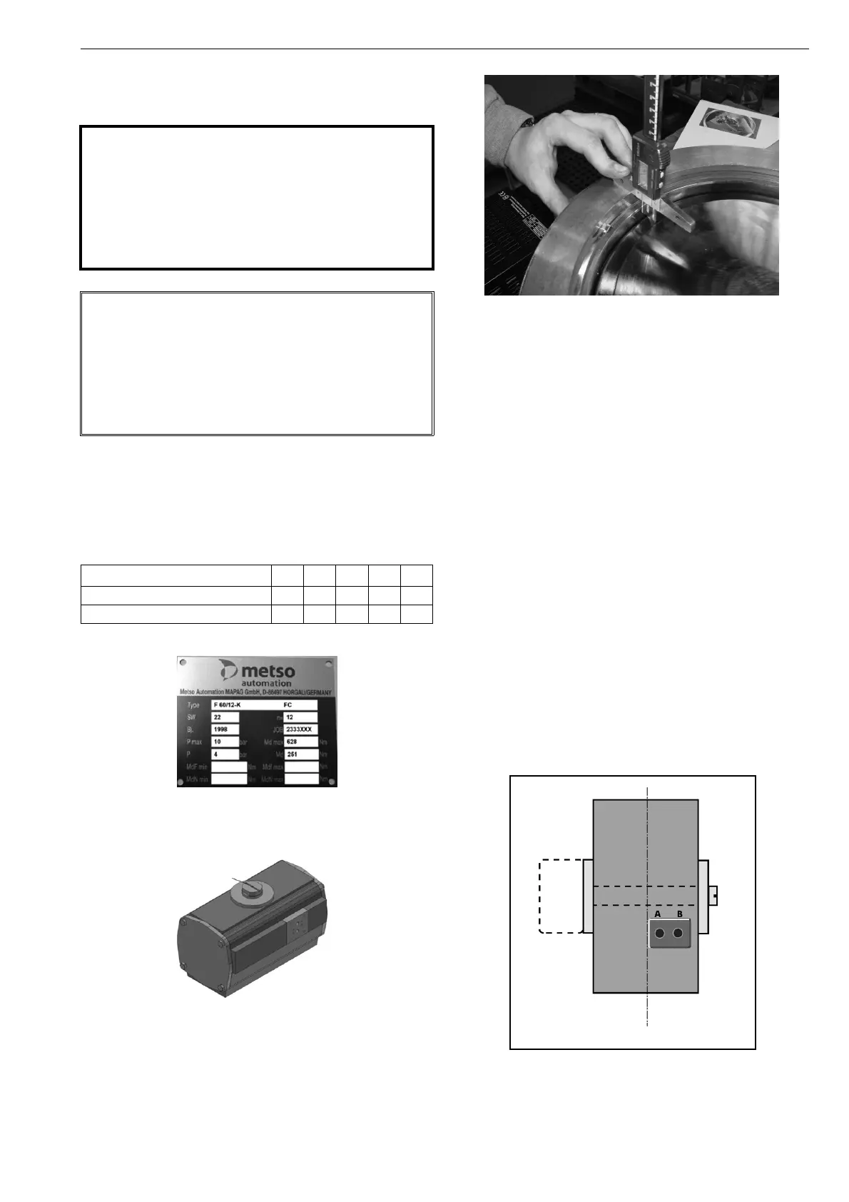
Figure 9 Identification plate of the actuator of drive
Figure 10 The marking on the selector shaft corresponds to
the position of the on/off disc
Figure 11 Checking the closed position by means of depth
measurements
4.3 Mounting
Proceed as follows for installing the actuator:
□ Before attaching the actuator, set the valve in the closed
position.
□ Push the selector shaft of the actuator carefully onto the
valve shaft. Note that the actuator adjoins the bracket
exactly and is aligned with it, so that no stresses may
occur at the valve shaft.
□ Note that the marking on the drive shaft corresponds to
the position of the on/off disc (see Figure 10).
□ Secure the actuator to the bridge using the four screws
and tighten them on their cross tips. Information: The
housing of F1 -series actuator are composed of an alu-
minum material. The fastening threads may be dam-
aged by uncontrolled tightening.
→ Refer to 12.8 for
torque values
□ Now finally check the closed position of the valve once
again by means of several depth measurements,
wherein the determined data may vary from one
another by a max. of 0.3 mm (see Figure 11).
□ Finally connect the energy supply (see figure 12).
Figure 12 Connecting the pneumatics
CAUTION:
Note the weight of the valve or the entire servo unit
while handling!
The actuator may not be detached from the valve if
the pipeline is under pressure as a consequence of a
dynamic torque!
Do not dismantle any actuator with spring retainer
without securing the spring with a stop screw!
NOTE:
Before dismantling the actuator, note the mounting
position and opening angle of the valve with respect to
actuator and positioner/ limit switch so that the correct
function is maintained in the following assembly.
You must install the actuator, so as to allow free access to
it any time. This especially applies also to a possible
“emergency stop” operation by hand.
actuator size 30 60 120 250 500
double-acting type F1A [kg] 10 16 28 51 100
single-acting type F1F [kg] 13 21 56 85 160
Mounting
bracket
A = Air open
B = Air close
 Loading...