2 BAR 70 en 5
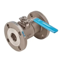
The valves data are shown on the identification plate
attached to the body.
In the service case, the factory number (unique no.) is the
one that uniquely designates the valve. This number is also
attached to the body in case the identification plate can no
longer be found.
Further information:
Job no. = job number at Metso Automation
MAPAG
Type = Type code of the valve
body = body material
YEAR = Year of manufacture
NPS or DN = Size; CL or PN = pressure class
Pressure class
ID no. = Customer identification number
Tag no. = Valve and fittings number
TS. = Operating temperature of the
valve in °C (medium)
PS = Operating pressure of the valve
P.O.NO. = Order number of the customer /
consignment number
CV = Flow rate in gallons/min
EX II 2GcTx = Atex sign
CE = CE0036 (notified body for PED)
The following markings are made (see Figure 4) for display-
ing the disc position in the installed valve:
□ CLOSED sign with colored marking on the body.
□ Colored marking on the valve shaft.
If both red markings are (align axially), the valve position is
"closed". The sealing element is on the side of the body on
which the “Closed” sign is mounted.
1.7 ATEX and CE -marking
The valve fulfills the requirements of the European Directive
97/23/EC regarding pressure-related equipment and is
marked according to this directive.
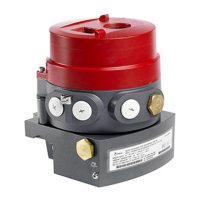
The ATEX and CE signs are displayed on the identification
plate (see Figure 3 Rating plate).
1.8 Contact
Please contact your local Metso partner.
You will find the contact information at:
www.metso.com/automation
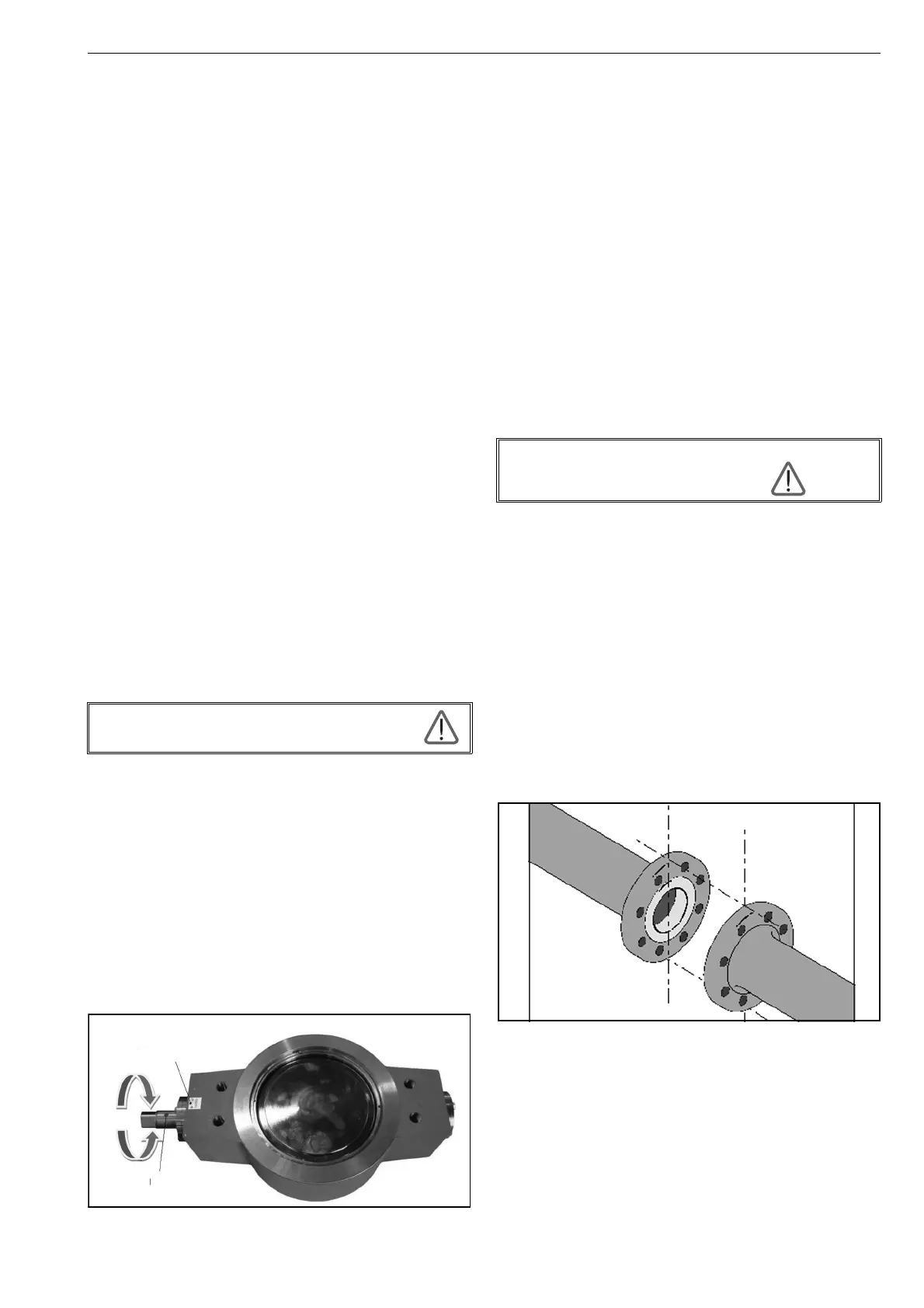
Figure 4 Direction of the actuator and position of the on/
off disc.
2 Transport, reception and storage
Check the valve including accessories for shipping damage.
Prior to installation, the valve is to be carefully stored in a
dry roofed room.
Storage temperature = -20° to 80 °C
Relative humidity 85% max. (non-condensing)
The valve must be warehoused with the factory-mounted
covers.
The valve should be transported on-site only a short while
before the installation.
The covers on the openings are to be removed for installing
the valve.
The valve is delivered in closed position.
A valve with an actuator and a spring retainer is delivered in
the position set by the spring (spring opens or closes).
3 Installation
3.1 Installation planning
Consider following aspects before assembly:
□ You must install the on/off (butterfly) valve, so as to
allow free access to the drive at any time.
□ Drives that are operated using electric, pneumatic or
hydraulic energy may be connected to the energy sup-
ply only after installing the on/off (butterfly) valve.
□ The flange holes of both pipeline ends must be exactly
aligned axially with each other, the sealing surfaces of
the opposite flanges must be parallel to each other. The
flange holes may not be distorted from one another, so
that the on/off (butterfly) valve is not exposed to any
stresses during assembly.
Figure 5 Alignment of the flanged pipes
Opening and closing similar to a water tap.
(viewed from the actuator side)
Close in
clockwise
direction
Open
counterclock-
wise direction
Marking drive shaft
Marking on the body
Assembly work at the on/off (butterfly)
valve shall be made only by
qualified personnel!
 Loading...