20 2 BAR 70 en
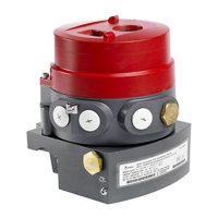
Figure 34 Cover removed
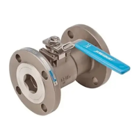
4. Place an extraction tool in the draw-off threads of the
bearing bushes (410) and remove the bearing bush by
carefully pulling it over the shaft that is still attached to
the body.
Figure 35 Dismantling the bearing bushes
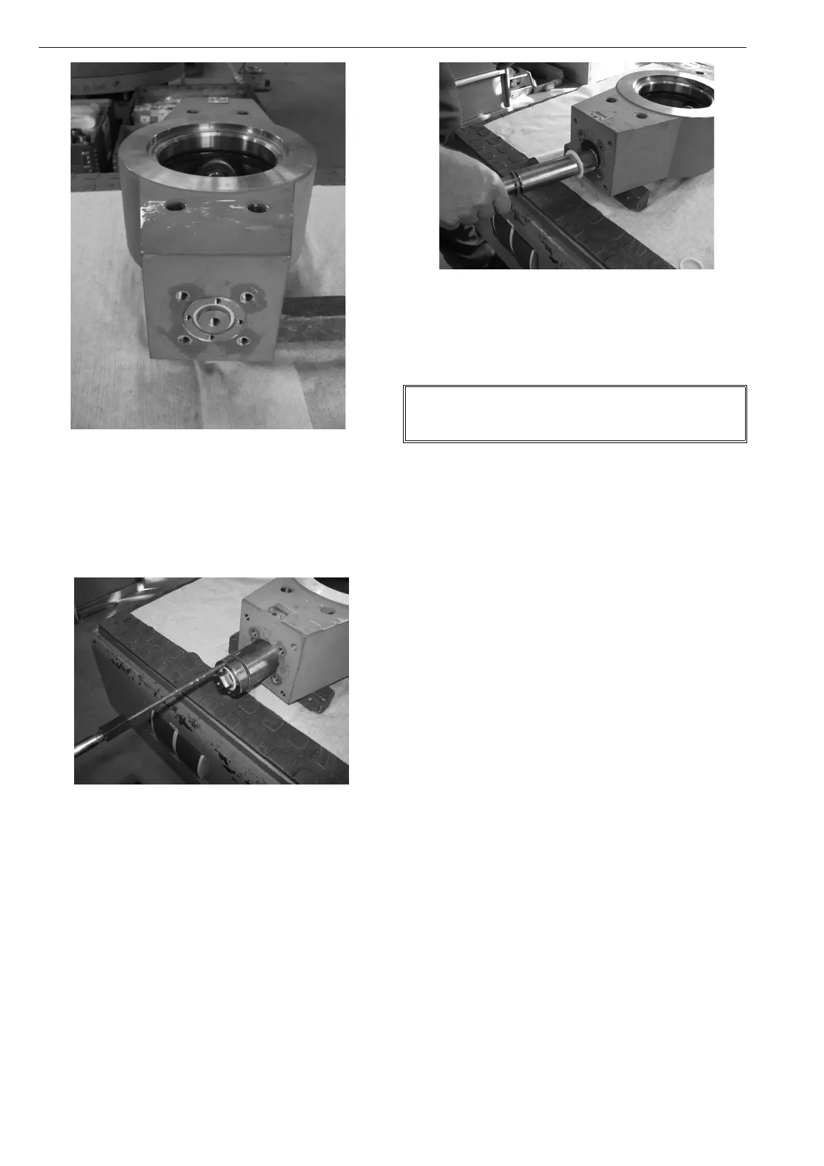
5. Subsequently remove the retaining o-ring (438) and
pull the shaft out of the disc and the body.
Figure 36 Dismantling the shafts
The parts can now be replaced by the recommended spare
parts sets under chapter 12.
6. Before assembly, all parts must be cleaned carefully.
7. Check the shaft for any trace of wear and tear. In case of
ridging or other damage it is strongly recommended to
replace the shafts as well (items 401 and 402)! The
shafts are not included in the spare parts sets and must
be ordered separately.
8. Assembly is accordingly done in the reverse sequence.
For easier assembly of the bearing bushes, the O-rings
(419, 471) can be slightly lubricated using special PTFE
grease (previously check for admissibility of lubri-
cants!). Install the bearing bushes (410) as a whole with
extreme caution for avoiding any damage to the seals.
9. Install support rings (406), O-rings (471) and cover (430,
437). Tighten the cover screws (434) using a suitable
torque wrench in view of the torques indicated in chap-
ter 12.8.
10. Check the high-performance valve for its seal-tightness
before reinstallation. You will find the installation
instructions in chapter 3.3.
There are separate "Spare sets" for the special design
version for clamp type socket. For this, see also chap-
ter 12.3 – Exploded view and parts list.
 Loading...