Mettler Electronics Corp.— Rev.J_09/13/17
30
4.7 Electrode Positioning
1. General information
Placement of electrodes may be by the quadpolar,
bipolar or monopolar techniques. Proper positioning
and contact will insure treatment comfort and
efficiency. Electrodes should never be placed in such
a manner as to produce current flow through the
cardiac area. For safe operation of the Sonicator Plus
930, review contraindications, warnings, precautions
and Side Effects/Adverse Reactions in sections 5.4,
5.5, 5.7 and 5.8 before positioning electrodes.
2. Preparation of the skin prior to electrode application
To insure the efficient current conduction necessary
for proper treatment, certain preparations must be
made. Cleaning or wetting should eliminate any
impairment to current conduction on the patient’s
skin such as an oily or dry surface, or excessive hair
coverage. Shaving may be necessary depending upon
the density of hair coverage. Failure to provide for
maximum current conduction efficiency could result
in skin irritation relating to an increase in current
density at the electrode site.
Using reusable electrodes for longer periods of time
than those recommended by the package insert could
result in ineffective treatments or cause skin irritation.
Care should be taken to ensure application of the total
electrode surface area to the patient's skin prior to
commencing treatment.
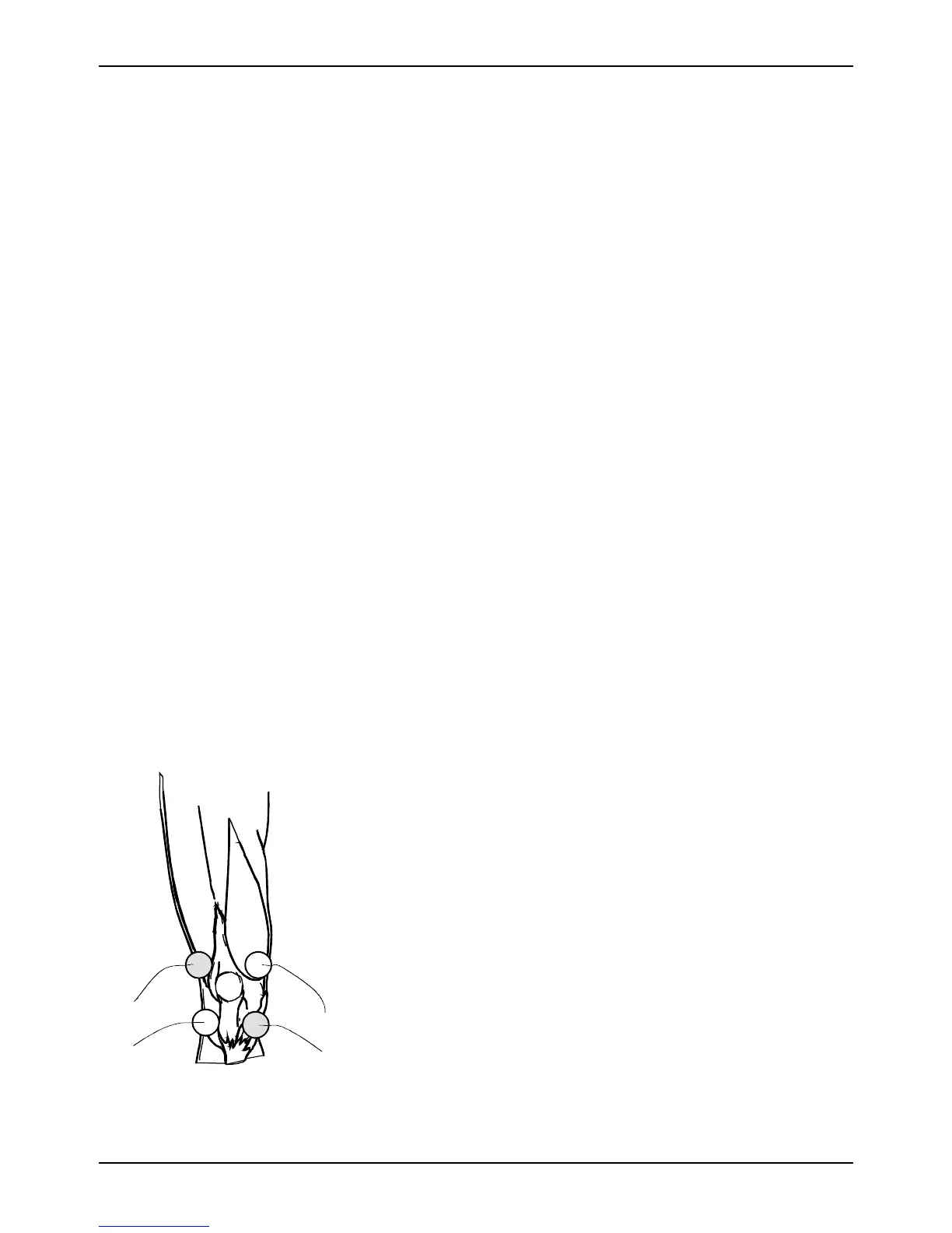
Figure 4.3—Quadpolar Electrode
Placement
Technique
3. Quadpolar electrode application technique
Quadpolar techniques should be used with the
“Interferential” waveform. The electrodes from
Channel 1 are placed diagonally from each other.
While the electrodes from Channel 2 are placed
diagonally across from each other to form an “X” over
the treatment area. The zone of maximum
interference between the two channels occurs roughly
in the center of the “X”.
Constantly changing the intensity levels of the two
channels will change the interference pattern felt by
the patient. Pressing the amplitude modulation key
will constantly change the intensity of the outputs of
the two channels during treatment, increasing the
area covered by the interference pattern.