MCS-BMS-GATEWAY Startup Guide REVISION 4.5
42
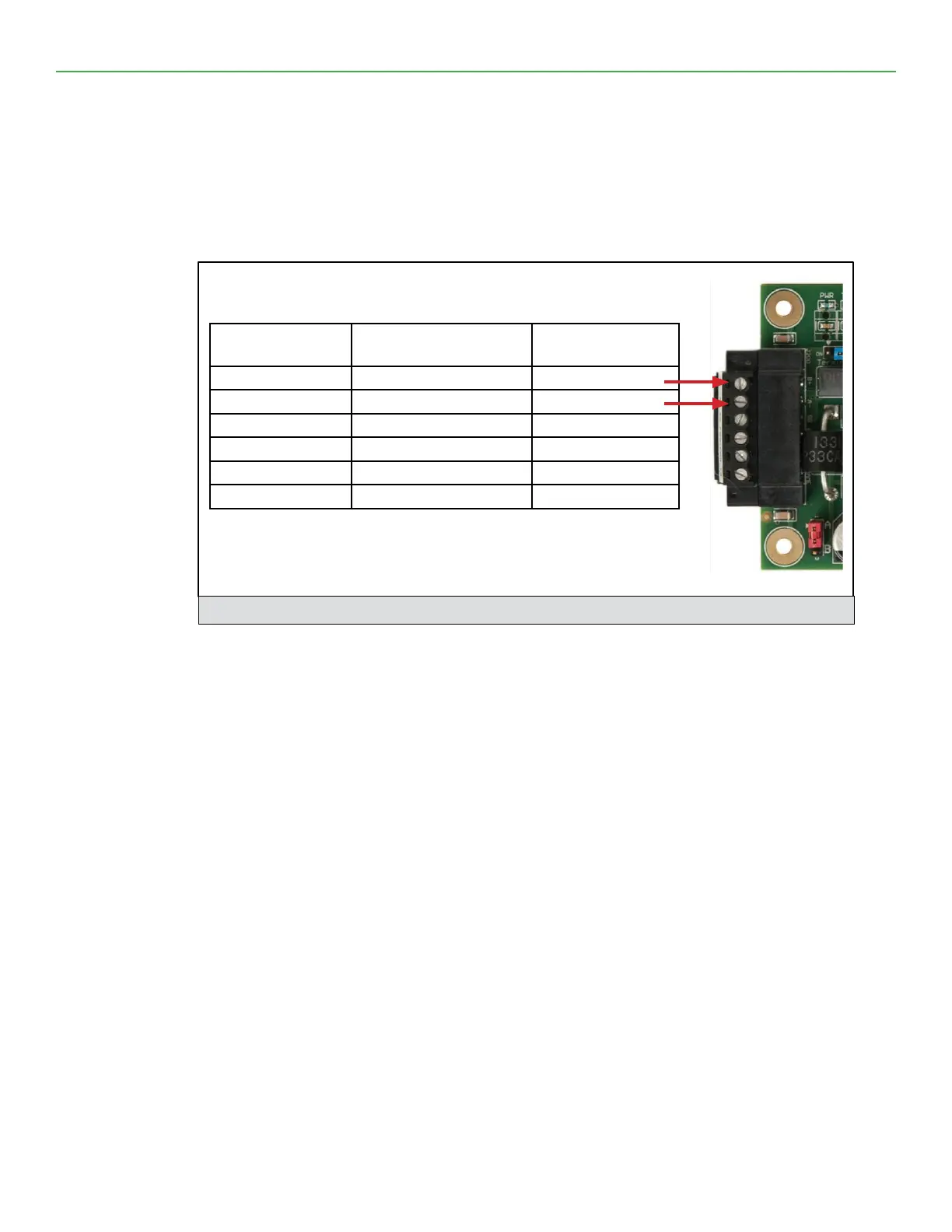
4.3. Device Connections to MCS-BMS-GATEWAY-NL-NL
MCS-BMS-GATEWAY-NL-NL 6 Pin Phoenix connector for RS-485 Devices.
• Pins 1 through 3 are for RS-485 devices.
• The RS-485 GND (Pin 3) is not typically connected
• Pins 4 through 6 are for power. Do not connect power (wait until Section 3.4).
Figure 8: Power and RS-485 Connections
Device Pins
MCS-BMS-GATEWAY-
NL-NL Pin #
Pin Assignment
Pin RS-485 + Pin 1 RS-485 +
Pin RS-485 - Pin 2 RS-485 -
Pin GND Pin 3 RS-485 GND
Power In (+) Pin 4 V +
Power In (-) Pin 5 V -
Frame Ground Pin 6 FRAME GND