MCS-BMS-GATEWAY Startup Guide REVISION 4.5
47
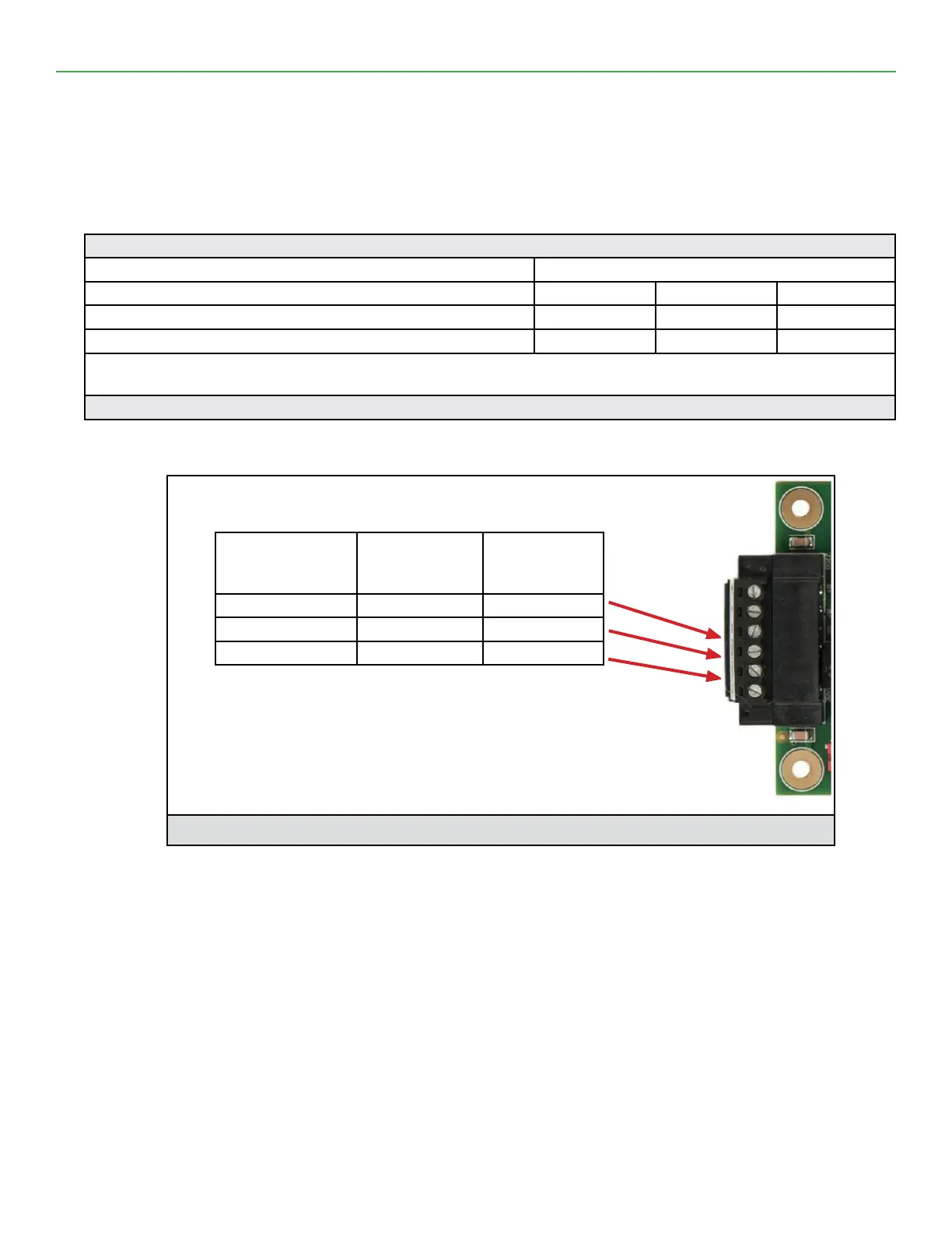
4.7. Power-Up MCS-BMS-GATEWAY-NL
Apply power to MCS-BMS-GATEWAY-NL-NL as show below in Figure 13. Ensure that the power supply used
complies with the specications provided in chapter 9.
1. MCS-BMS-GATEWAY-NL accepts either 9-30VDC or 12-24 VAC on pins 4 and 5.
2. Frame GND should be connected.
Power Requirement for MCS-BMS-GATEWAY-NL External Gateway
Current Draw Type
MCS-BMS-GATEWAY-NL Family 12VDC/VAC 24VDC/VAC 30VDC
FPC – ED4 (Typical) 210mA 130mA 90mA
FPC – ED4 (Maximum) 250mA 170mA 110mA
NOTE: These values are ‘nominal’ and a safety margin should be added to the power supply of the host system.
A safety margin of 25% is recommended.
Figure 12: Required current draw for the MCS-BMS-GATEWAY-NL
Power to MCS-
BMS-GATEWAY-
NL
MCS-BMS-
GATEWAY-NL
Pin #
Pin
Assignment
Power In (+) Pin 4 V +
Power In (-) Pin 5 V -
Frame Ground Pin 6 FRAME GND
Figure 13: Power Connections