Connecons
User Guide
© 2023 Microchip Technology Inc. and its subsidiaries
DS-50003529B - 15
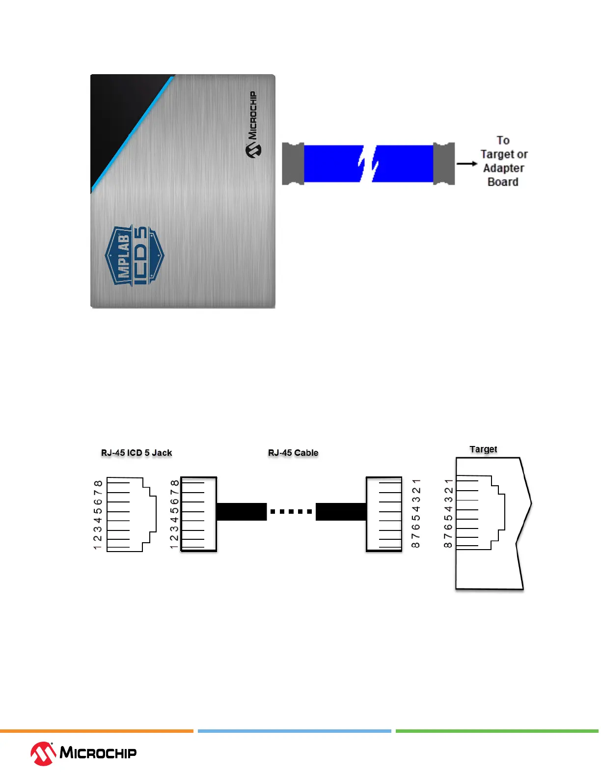
Figure 3-4. MPLAB ICD 5 Unit to Target Connecon
3.3.1 Connecng the Debugger to an RJ-45 Target via an RJ-45 Type Cable
The MPLAB ICD 5 In-Circuit Debugger has an RJ-45 connector for communication to the target.
Connect the RJ-45 type cable into the RJ-45 connector. Connect the other end of the cable to the
RJ-45 connector on the target.
Refer to the gure below for the pinouts for this connection.
Figure 3-5. RJ-45 Connecons to Target
3.3.2 Target Connecon Pinouts
The programming connector pin functions are dierent for various devices and interfaces. Refer
to the following pinout tables for debug and data stream interfaces. Legacy 6-pin RJ-11 cable can
also be used, however target interfaces which use pins 1 (TMS/SWDIO) and 8 (TDI/MOSI) can not be
programmed or debugged.
Note: Refer to the data sheet for the device you are using as well as the application notes for the
specic interface for additional information and diagrams.