Connecons
User Guide
© 2023 Microchip Technology Inc. and its subsidiaries
DS-50003529B - 16
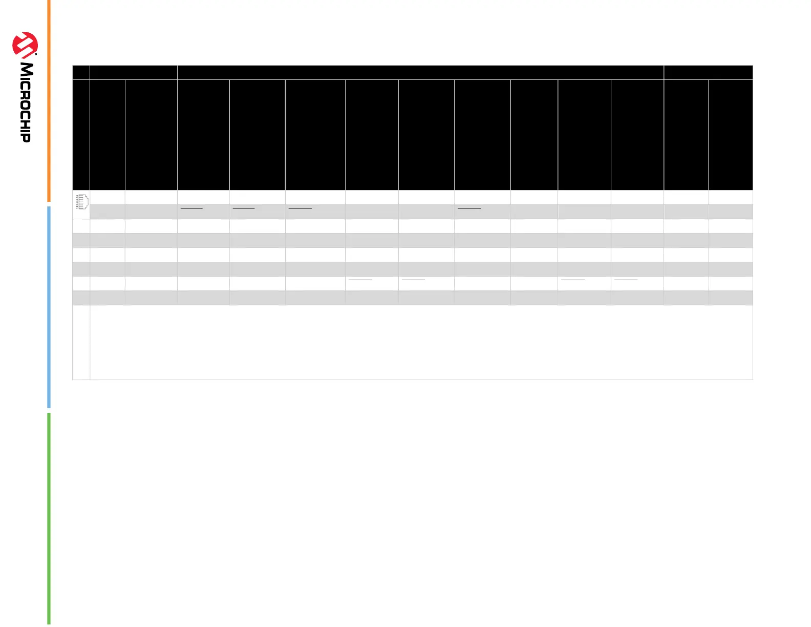
Table 3-2. Pinouts for Debug Interfaces
rotatethispage90 MPLAB ICD 5 DEBUG TARGET
4
8-Pin Modular Connector
1
Pin #
Pin Name
ICSP
™
(MCHP)
MIPS EJTAG
Cortex
®
SWD
AVR
®
JTAG
AVR debugWIRE
AVR UPDI
AVR PDI
AVR ISP
AVR TPI
8-Pin Modular Connector
6-Pin Modular Connector
8 TTDI TDI TDI MOSI 1
7 TVPP MCLR /Vpp MCLR RESET RESET
3
2 1
6 TVDD VDD VDD/VDDIO VDD VTG VTG VTG VTG VTG VTG 3 2
5 GND GND GND GND GND GND GND GND GND GND 4 3
4 PGD DAT TDO SWO
2
TDO DAT
3
DAT MISO DAT 5 4
3 PGC CLK TCK SWCLK TCK SCK CLK 6 5
2 TAUX RESET RESET/dW CLK RESET RESET 7 6
1 TTMS TMS SWDIO
2
TMS 8
rotatethispage90
1. Black (8-pin) cable must be used for EJTAG, JTAG, SWD and ISP.
2. SWO is used for trace. SWDIO is for debug.
3. Pin may be used for High-Voltage Pulse reactivation of UPDI function depending on device. See device data sheet for details.
4. These are example target connectors that are assumed similar to the debug unit (modular).