Operaon
User Guide
© 2023 Microchip Technology Inc. and its subsidiaries
DS-50003529B - 43
uses the internal in-circuit debug hardware of the target Flash device to run and test the application
program. These two steps are directly related to MPLAB X IDE operations:
1. Programming the code into the target and activating special debug functions (see the next
section for details).
2. Using the debugger to set breakpoints and run.
For more information, refer to the MPLAB X IDE WebHelp.
If the target device cannot be programmed correctly, the MPLAB ICD 5 will not be able to debug it.
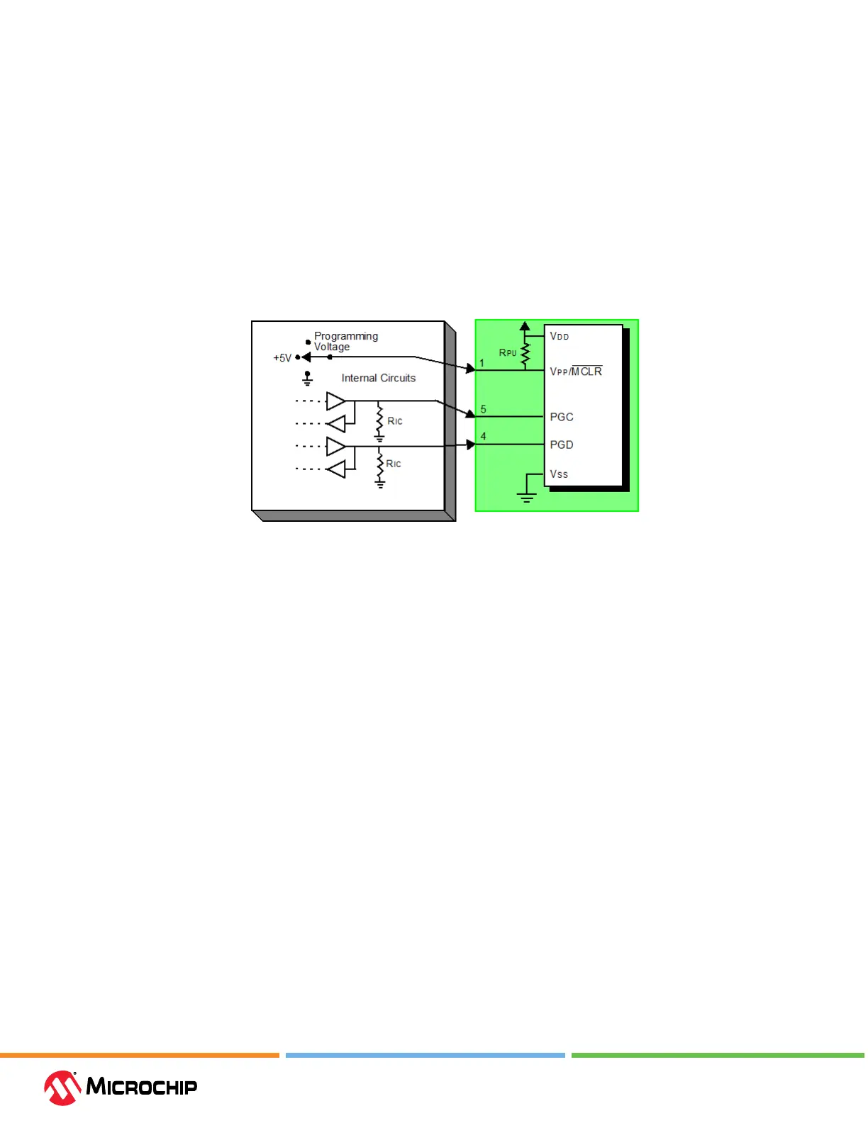
A simplied diagram of some of the internal interface circuitry of the MPLAB ICD 5 is shown in the
gure below. In the gure, Rpu=10 kΩ typical and Ric=4.7 kΩ.
Figure 4-4. Proper Connecons for ICSP Programming
For programming, no clock is needed on the target device, but power must be supplied. When
programming, the debugger puts programming levels on VPP/MCLR, sends clock pulses on PGC,
and serial data via PGD. To verify that the part has been programmed correctly, clocks are sent
to PGC and data is read back from PGD. This sequence conrms the debugger and device are
communicating correctly.
4.4.2.1 ICSP Circuits That Will Prevent a Debug Tool From Funconing
The gure below shows the active debugger lines with some components that will prevent the
MPLAB ICD 5 In-Circuit Debugger from functioning.