Debugger Features
User Guide
© 2023 Microchip Technology Inc. and its subsidiaries
DS-50003529B - 51
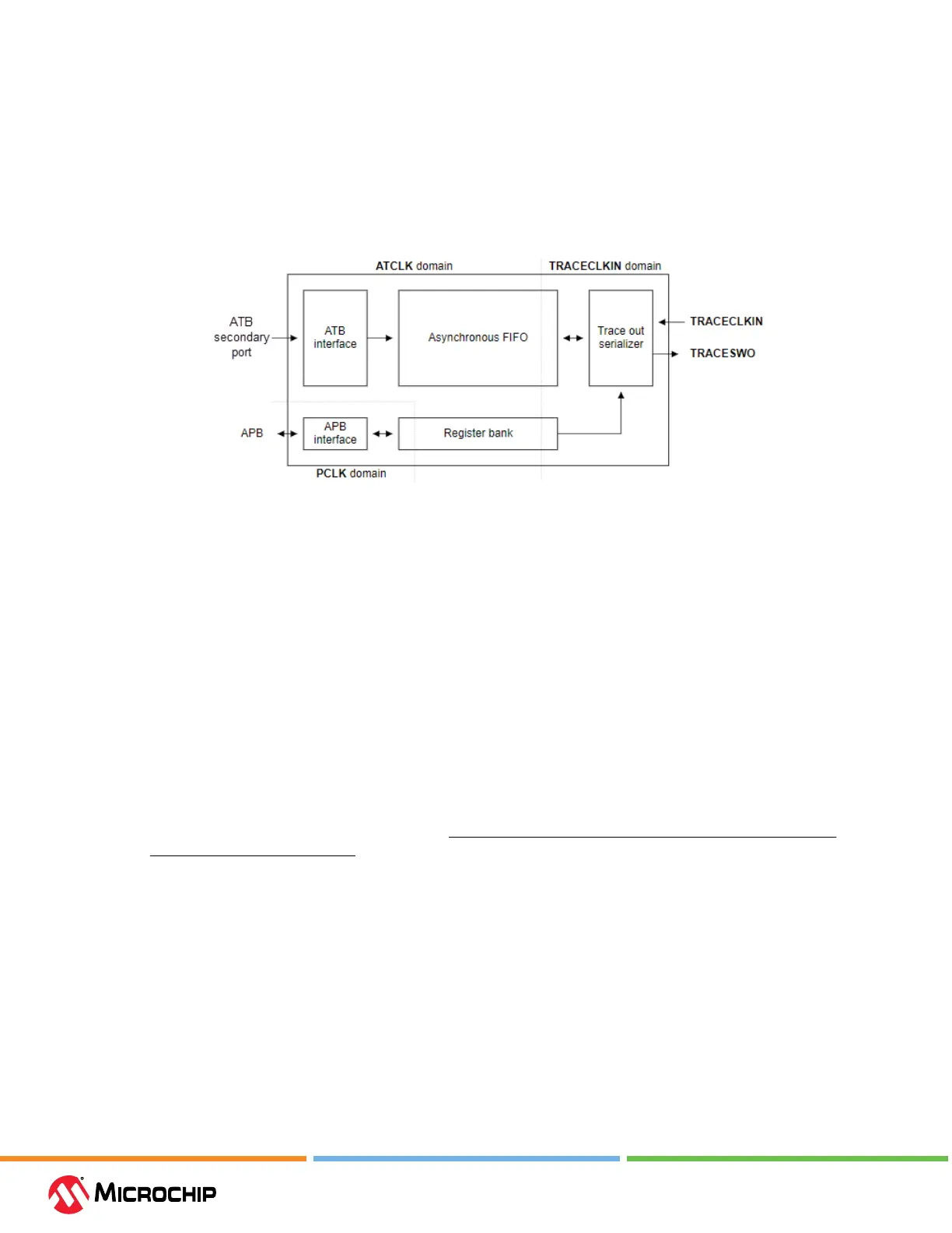
• an 8-bit ATB input.
• no synchronous trace output, that is, no TRACEDATA, TRACECTL, or TRACECLK pins.
• no support for ush, because this is not required.
• no support for triggering.
• no external inputs and outputs (EXTCTLIN and EXTCTLOUT are not implemented).
Figure 5-2. SWO Block Diagram
5.4.3 Requirements for ITM/SWO Trace
The following is required to use trace for SAM devices:
• MPLAB X IDE v6.10 or greater.
• A target board with debug and trace connections to a device that supports SWO trace.
• For debug and trace support, use one of the following:
– MPLAB ICD 5 Cortex-M Trace Adapter Board
– ICD 5 JTAG Adapter Board (Note: SWO pin multiplexed with JTAG pins)
– a target board with a connector to the 8-pin at cable
5.4.4 Hardware Setup
Preliminaries
1. Use USB communication between the PC and MPLAB ICD 5. Other communication types do not
support trace.
2. Find devices that support ITM trace – see Help>Release Notes> Debug Features Support>Hardware
Tool Debug Features by Device.
3. Design the target board to have a connector for debugger-target communication and for trace
pins if using SAM 3.3.3. Debugger Adapter Board. Alternately design the target board to connect
to the cable with pins for both debug and trace.
4. When using trace, the TRACESWO pin on the target is used. Therefore you cannot use another
function multiplexed on that pin.
Set Up Hardware
To use the ITM/SWO feature:
1. The target board should be unpowered.
2. Install the communication cable between the debugger or adapter board and the
communication connector on your target board.