Debugger Funcon Summary
User Guide
© 2023 Microchip Technology Inc. and its subsidiaries
DS-50003529B - 79
Timer Interval Units Select a sampling interval unit:
• microseconds
• milliseconds
• seconds
• instruction cycles
32-Bit Devices
Options available on this page depend on the trace/proling features of the project device.
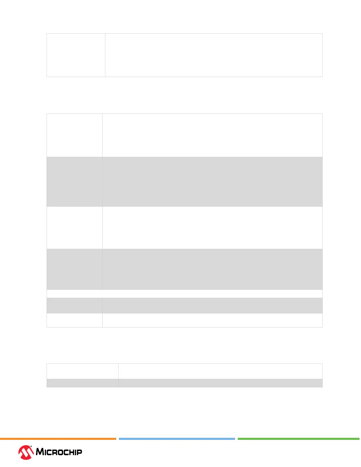
Table 9-8. Trace/Proling Opon Category
Data Collection
Selection
Enable/Disable data collection.
• O - Do not collect target data.
• Instruction Trace/Proling.
• User Instrumented Trace.
• Power Monitor (Target Power Sampling).
Data File Path and
Name
Enter or change the path and/or name of the le used to store data.
• Enter le name (path will be relative to project) – Recommended.
• Enter a path and le name (path will be absolute).
• Browse (...) to a le, select “Absolute,” select the le, and click Save (path will be absolute).
Note: Do not select “Relative” when browsing to a le or MPLAB X IDE will not be able to nd the
le. When you run, you will receive a warning message that the path does not exist.
Data File Maximum Size
(bytes)
Set the maximum size of the data le.
Each line of instruction trace data in a trace data le requires 13 bytes when using the debugger.
Target power sampling will take 12 bytes or 18 bytes (with PC data) per sample.
The le size may be adjusted down to be a multiple of one of those byte sizes depending upon
the trace type selected. Other trace data types may use record byte sizes dierent from those
described above.
Data Buer Maximum
Size (bytes)
Set the size of the data buer, up to 54600 bytes (on board the debugger unit).
For trace/sampling data that is buered in memory while the target is running, individual trace or
sample entry sizes vary depending on the trace/sample type and the device and tool being used. It
is normally good to make this buer as large as possible.
For example, PIC32 instruction trace takes 8 bytes per “frame” which can produce over 50 13-byte
ICD 5 instruction trace entries in a trace le.
User Instrumented Trace Items
Disable Trace Macros Check to temporarily disable trace macros or uncheck to enable trace macros.
To disable trace, remove all macros and select “O” under “Data Collection Selection.”
Communications
Medium
Select the trace medium, if available, from the following (device-dependent): Native
9.2.7 Power
Select whether or not to power the target from the debugger.
Table 9-9. Power Opon Category
Power Target Circuit from ICD 5 Check to use power from the debugger.
Uncheck to power the target from its own power supply.
Voltage Level If option above checked, select the target Vdd (2.375V - 5.5V) that the debugger will provide.
9.2.8 Clock
Enter the runtime clock (instruction) speed under this option category. This does not set the speed,
but informs the debugger of its value for runtime watch, data capture and trace.