Hardware Specicaon
User Guide
© 2023 Microchip Technology Inc. and its subsidiaries
DS-50003529B - 91
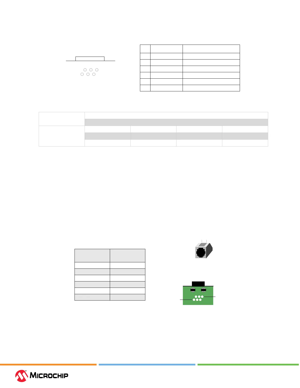
Figure 10-8. 6-Pin Standard Pinout
1
2
3
4
5
6
Pin Name Function
1V
PP Power
2V
DD_TGT Power on target
3 GND Ground
4 PGD (ICSPDAT) Standard Com Data
5 PGC (ICSPCLK) Standard Com Clock
6- Reserved
Bottom of
Standard Socket
Target Board
Table 10-5. Electrical Logic Table
Logic Inputs V
IH
= V
DD
x 0.7V (min.)
V
IL
= V
DD
x 0.3V (max.)
Logic Outputs V
DD
= 5V V
DD
= 3V V
DD
= 2.3V V
DD
= 1.65V
V
OH
= 3.8V min. V
OH
= 2.4V min. V
OH
= 1.9V min. V
OH
= 1.2V min.
V
OL
= 0.55V max. V
OL
= 0.55V max. V
OL
= 0.3V max. V
OL
= 0.45V max.
10.6.3 Modular Cable and Connector
For standard communication, a modular cable connects the debugger and the target application.
The specications for this cable and its connectors are listed below.
10.6.3.1 Modular Connector Specicaon
• Manufacturer, Part Number – AMP Incorporated, 555165-1
• Distributor, Part Number – Digi-Key, A9031ND
The following table shows how the modular connector pins, for an application, correspond to the
microcontroller pins. This conguration provides full in-circuit debugger functionality.
Figure 10-9. Modular Connector Pinout of Target Board
Modular
Connector Pin
Microcontroller
Pin
6 Reserved
5 RB6
4RB7
3 Ground
2V
DD Target
1 VPP
1
6
Bottom View of Modular Connector
Pinout on Target Board
16
Front View of Modular
Connector on Target Board
10.6.3.2 Modular Plug Specicaon
• Manufacturer, Part Number – AMP Incorporated, 5-554710-3