© Microhard 27
3.0 Hardware Features
Pin Name No. Description Dir
Serial CTS 46 Clear To Send. Active low output. O
Serial RTS 48 Request To Send. Active low input. I
ETH0 LINK_LED 47 Active high output indicates Ethernet port 0 link status. Active high, cannot drive
LED directly. Requires current limiting resistor. 8mA maximum.
O
ETH4 LINK_LED 49 Active high output indicates Ethernet port 4 link status. Active high, cannot drive
LED directly. Requires current limiting resistor. 8mA maximum.
O
Console_RxD 50 Console Port Receive Data. Logic level input into the modem. I
Console_TxD 52 Console Port Transmit Data. Logic level Output from the modem. O
USBDM 53 USB D- signal; carries USB data to and from the USB 2.0 PHY
USBDP 55 USB D+ signal; carries USB data to and from the USB 2.0 PHY
RESET 70 Active low input will reset module I
USB_MODE 72 Indicates if the interface is in host/device mode. 0 = Device (Connected through
1K resistor to GND), 1 = Host.
I
V
CC
85,87,
89,91
Positive voltage supply voltage for the digital section of the module (3.3V). I
V
RF
93,95,
97,99
Positive voltage supply voltage for the radio module (3.3-5V). I
Table 3-3: pMDDL5824 Pin Description (continued)
All serial communications signals are logic level (0 and 3.3V). DO NOT connect RS-232 level (+12, -
12VDC) signals to these lines without shifting the signals to logic levels.
See Appendix D: Sample Interface Schematic for a sample schematic that can be used to interface to
the pMDDL5824 OEM module.
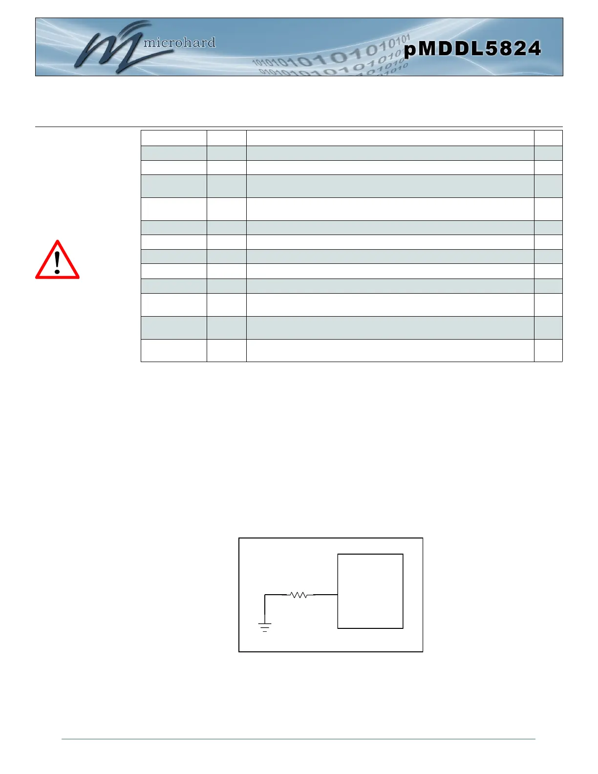
3.1.4 USB Device Mode
The pMDDL5824 can be set to operate as a USB Device. When set as a USB device, Microhard
Composite Drivers can be installed on a USB Host to provide Ethernet and Serial functionality to the USB
port on the pMDDL5824. To enable USB Device mode, Pin 72 must be connected to GND through a 1K
resistor as shown below:
Caution: During power up
or reset, output pins from
the Pico are in an unknown
state. It is advised to use
pull up or pull down
resisters as appropriate.
Drawing 3-6: pMDDL5824 USB Device Mode
pMDDL5824
GND
1 kΩ
72
USB Mode