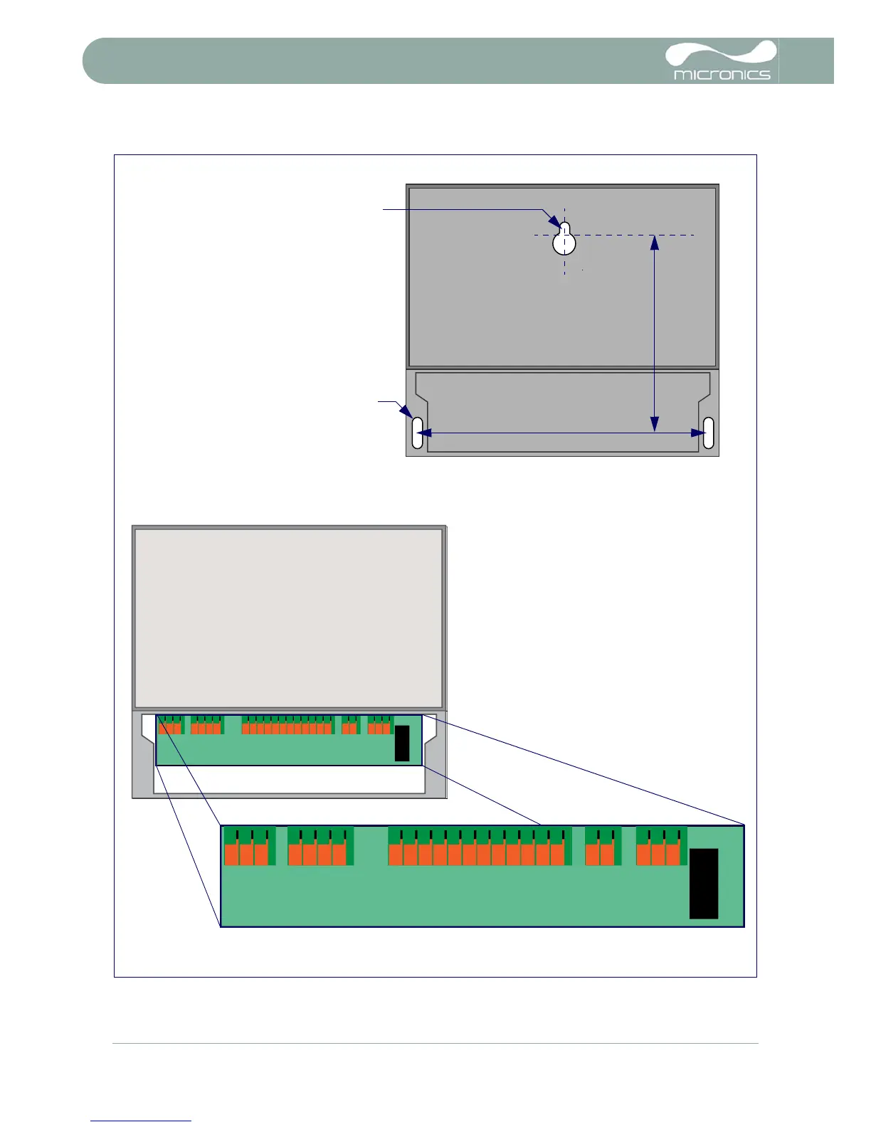
EasyManua.ls Logo

Micronics U3000 - Page 12

Micronics U3000
61 pages
To Next Page IconTo Next Page
To Previous Page IconTo Previous Page
Loading...
2: Installation
8 U3000/U4000 User Manual
(Issue 2.0)
Figure 2.1 U3000/U4000 Mounting and connection details
GND
TxD
RxD
mA+
mA-
PULSE+
PULSE-
ALARM1+
ALARM1-
ALARM2+
ALARM2-
EXPIO#1
EXPIO#2
EXPIO#3
EXPIO#4
EXPIO#5
EXPIO#6
EXPIO#7
EXPIO#8
24V+
24V-
230V -L
230V-N
230V-E
141mm
198mm
M4 Screw Slot
M4 Keyhole
Mounting Details
The instrument should be
securely wall-mounted using the
three fixing points shown.
Cable connections
All power and control cables enter
through cable glands located on the
bottom of the instrument and connect
to terminal blocks as shown.

Table of Contents

Related product manuals