Mounting, Connecting, and Wiring
System Components
2
HAWK MV-4000 Smart Camera Guide 2-13
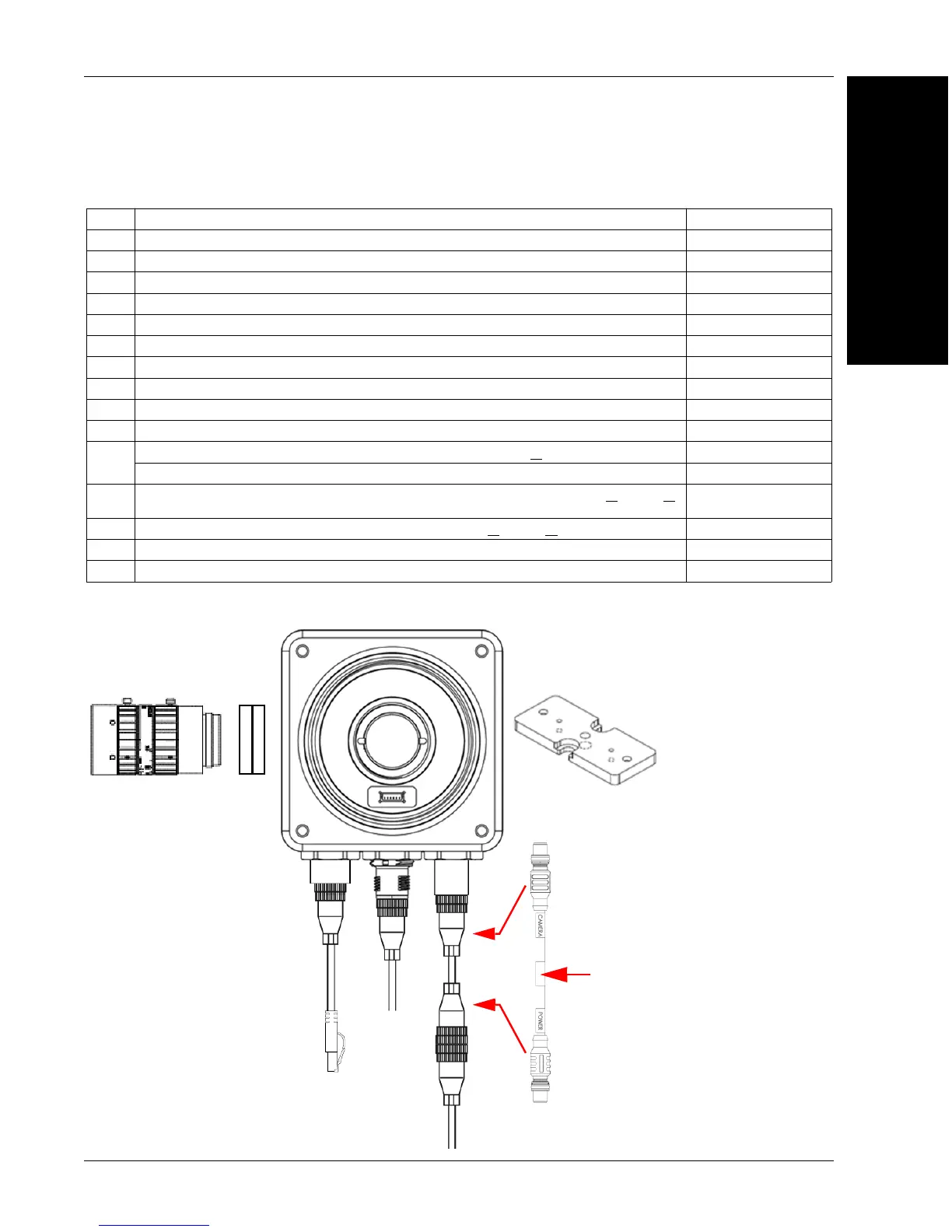
Hardware Configurations
Standard Ethernet Configuration
Item Description Part Number
1 HAWK MV-4000 Smart Camera 8X1X-XXX0-010X
2 Lens, C-Mount 98-90001XX-01
3 IP67 Lens Cover for HAWK MV-4000, 50 mm or 70 mm (not shown) 98-900015X-01
4 Lens Extension Tube Set, 0.5 mm, 1 mm, 5 mm, 10 mm, 20 mm, 40 mm 98-CO206
5 Cable, HAWK MV-4000 Ethernet, X-CODE / RJ45 CAT 6A, 1 m, 3 m, or 5 m 61-9000134-0X
6 Cable, HAWK MV-4000 M12 to USB Socket or VGA / USB, 1 m 61-900014X-01
7 Cable, Adapter, HAWK MV-4000 to Accessory Cables / Power Supply (supplied with camera) 61-9000132-01
8 Cable, HAWK MV-4000 M12 to Flying Leads, 3 m (no adapter required) 61-9000151-01
9 QX Cordset, HAWK MV-4000 Adapter to QX-1 M12 Plug (Screw-On), 1 m or 3 m 61-0001XX-02
10 QX-1 Interface Device 98-000103-02
11
QX Photo Sensor, M12 4-Pin Plug, NPN, Dark On or Dark Off, 2 m or
99-000020-0X
Trigger Connector, 4-Pin Plug (Screw Terminal, Field-Wireable) (Self-Wiring) 20-610024-01
12
Y Cable, HAWK MV-4000 Adapter to Smart Series Illuminator and QX-1, Power or
On/Off or
Strobe, 1 m
61-900013X-01
13 Cable, QX-1 to Smart Series Illuminator, Continuous Power or
On/Off or Strobe 61-0002XX-01
14 Power Supply, 100-240VAC, +24VDC, M12 12-Pin Socket 97-000012-01
15 APG Mount, HAWK MV-4000 (Requires Universal Mount) 98-9000054-01
5
2
4
1
15
61-9000132-01
CAMERA End
POWER End
6
14
7
Power Supply
(12-Pin Socket)