Tasks
2. Connect the battery holder/TNC cable to the LFR.
Use power from the SyncServer to test signal strength nearby while graphing signal strength
over several days:
1. Connect the supplied 50 foot (15.24 m) RG-59 cable to the TNC connector on the LFR.
2.
Connect the RG-59 cable to the Radio connector on the rear panel of the SyncServer.
Signal Quality
The Signal Quality LED (located on the underside of the LFR) indicates:
n
Once per second on/off: Good position, strong signal
n
Irregular/intermittent/flicker: Poor position, weak signal
n
Solid On: No signal
Positioning the Antenna
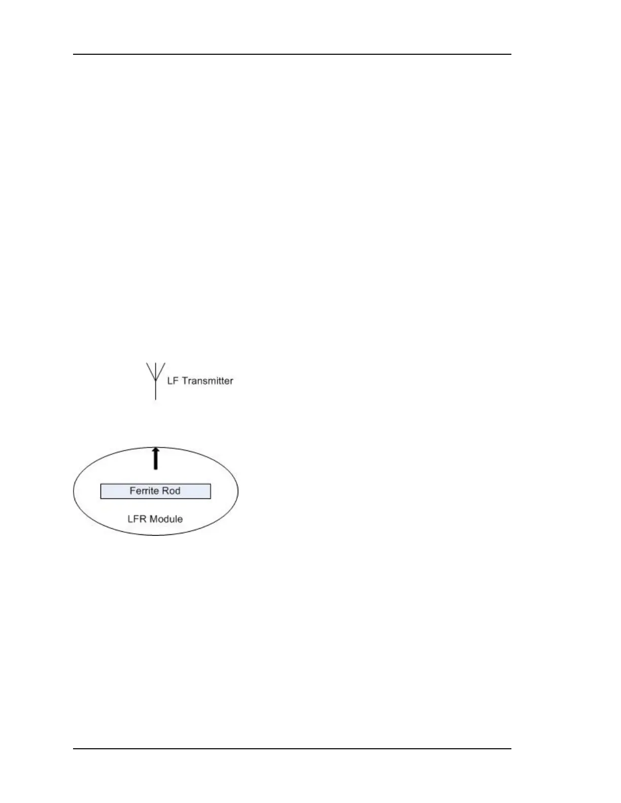
The LFR contains a ferrite rod antenna that isn't visible from the outside. The orientation of
the ferrite rod antenna has a significant effect on performance. The ferrite rod is in the
optimal position when:
n The black arrow on the top of the LFR is pointing toward the LF radio transmitter.
n The ferrite rod is horizontal.
Finding the Direction of the LF Radio Transmitter
Keeping the ferrite rod horizontal:
1. Hold the LFR near its intended location.
2. Find the weakest reception by rotating the LFR Antenna so the Signal Quality LED
shows "Solid On" or "Intermittent".
3. Rotate the LFR Antenna 90 degrees to the "best position". The signal quality LED should
show "Once per second on/off".
4. Temporarily mount the LFR antenna in this location, preserving the orientation of the fer-
rite rod.
Page 172..........................................................................997-01520-02 Rev. F1