EasyManua.ls Logo

Midea LSBLG320/MZ - Remote Control Wiring; Customer Wiring Terminal; Inside Electric Control Cabinet

Midea LSBLG320/MZ
113 pages
Print Icon
To Next Page IconTo Next Page
To Previous Page IconTo Previous Page
Loading...
DX type water-cooled screw chiller (PCB Control) MCAC-CTSM-2014-03
72
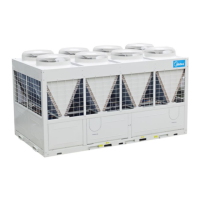
Chilled water pump wiring Diagram of 255320400485; 630; 860 models
Chilled water pump wiring Diagram of 970106012001260; 1490 models
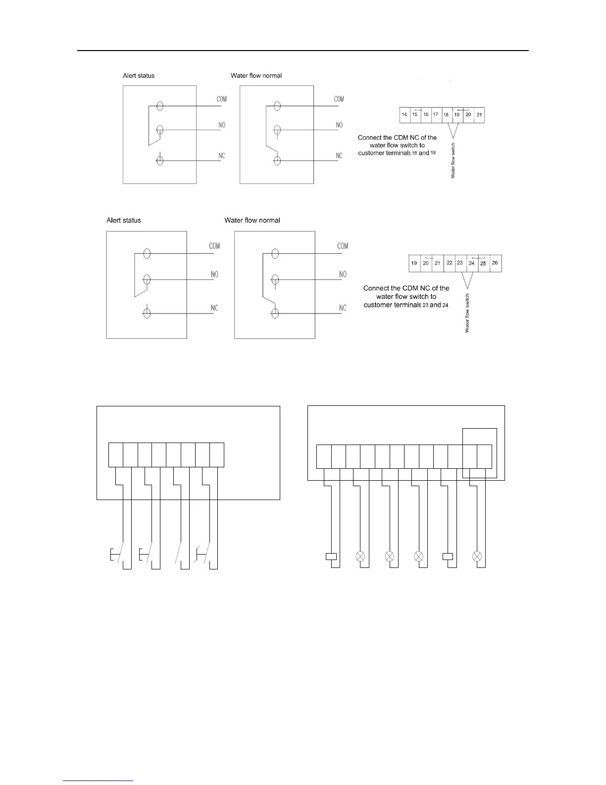
5) Remote control wiring
The wiring ports for remote start/stop, flow switch, water pump linked control, alarm indication, etc.
are reserved in the electrical cabinet of the unit, with the numbers shown in the diagram below.
Remote start/stop switch need to use inching switch.
Lamp input 220VAC.
Only double head
Inside electric control cabinet
Customer wiring terminal
Inside electric
control cabinet
Remote Start
Pump intermediate relay
Refrigeration lamp
1
2
3
4
5
6
7
8
Remote Stop
Flow switch
1
2
13
14
15
16
17
18
19
20
21
22
23
24
1# alarm lamp
2# alarm lamp

Table of Contents

Related product manuals