15
8.2 Application 2
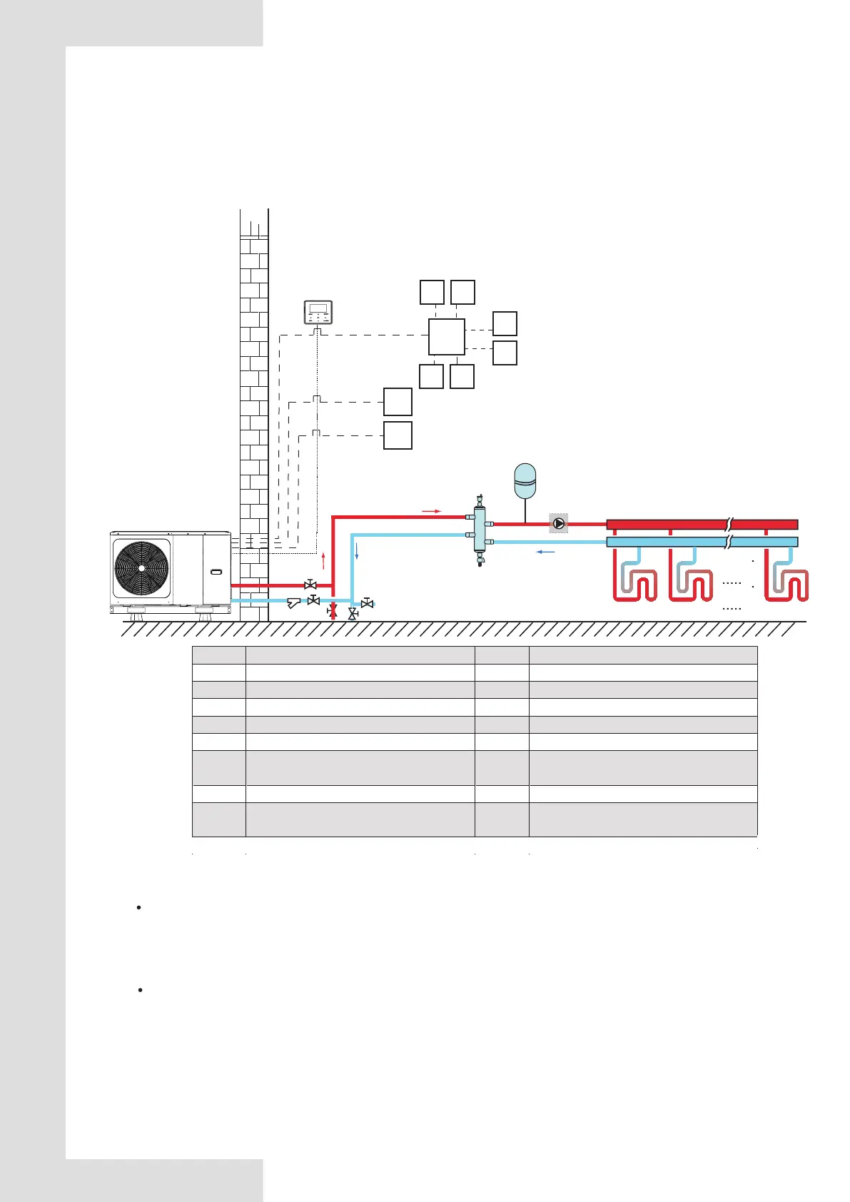
ROOM THERMOSTAT Control for Space heating or cooling need to be set on the user interface. It can be set
in three ways: MODE SET/ONE ZONE/DOUBLE ZONE. The molobloc can be connected to a high voltage room
thermostat and a low voltage room thermostat. A hydraulic adapter box can also be connected. Another six
thermostats can be connected to the hydraulic adapter box. Please refer to 9.7.6/6. “FOR ROOM THERMOSTAT” for
wiring. (see 10.6.6 "ROOM THERMOSTAT" for setting)
Code Assembly unit Code Assembly unit
1 Main unit 14 Shut-off valve (Field supply)
15 Filling valve (Field supply) 2
User interface
16 Drainage valve (Field supply)
4
Balance tank
(Field
supply)
19 Collector/distributor (Field supply)
4.1
Automatic air purge valve
21 Hydraulic adapter box (Optional)
4.2
Drainage valve
RT 1…7 Low voltage room thermostat (Field supply)
5
P_o: Outside circulation pump
(Field
supply)
RT8
High voltage
room
thermostat
(Field
supply
)
10
Expansion vessel
(Field
supply)
FHL
1…n
Floor heating loop (Field supply)
12
Filter (Accessory
)
Space heating
One zone control: the unit ON/OFF is controlled by the room thermostat, cooling or heating mode and outlet
water temperature are set on the user interface. System is ON when any “HL” of all the thermostats closes. When
all “HL” open, system turns OFF.
The circulation pumps operation
When the system is ON, which means any “HL” of all the thermostats closes, P_o starts running; When the
system is OFF, which means all “HL” close, P_o stops running.
5
4
4.2
4.1
10
FHL1 FHL2 FHLn
19
8.2.1 One zone control
Outdoor
1
Indoor
RT2 RT3
21
RT4
RT5
RT7
RT6
RT8
RT1
Modbus
15
16
14
12
14
2
16

 Loading...


