19
Assembly unit
Coding
1
2
3
4
5
6
7
8
9
10
11
12
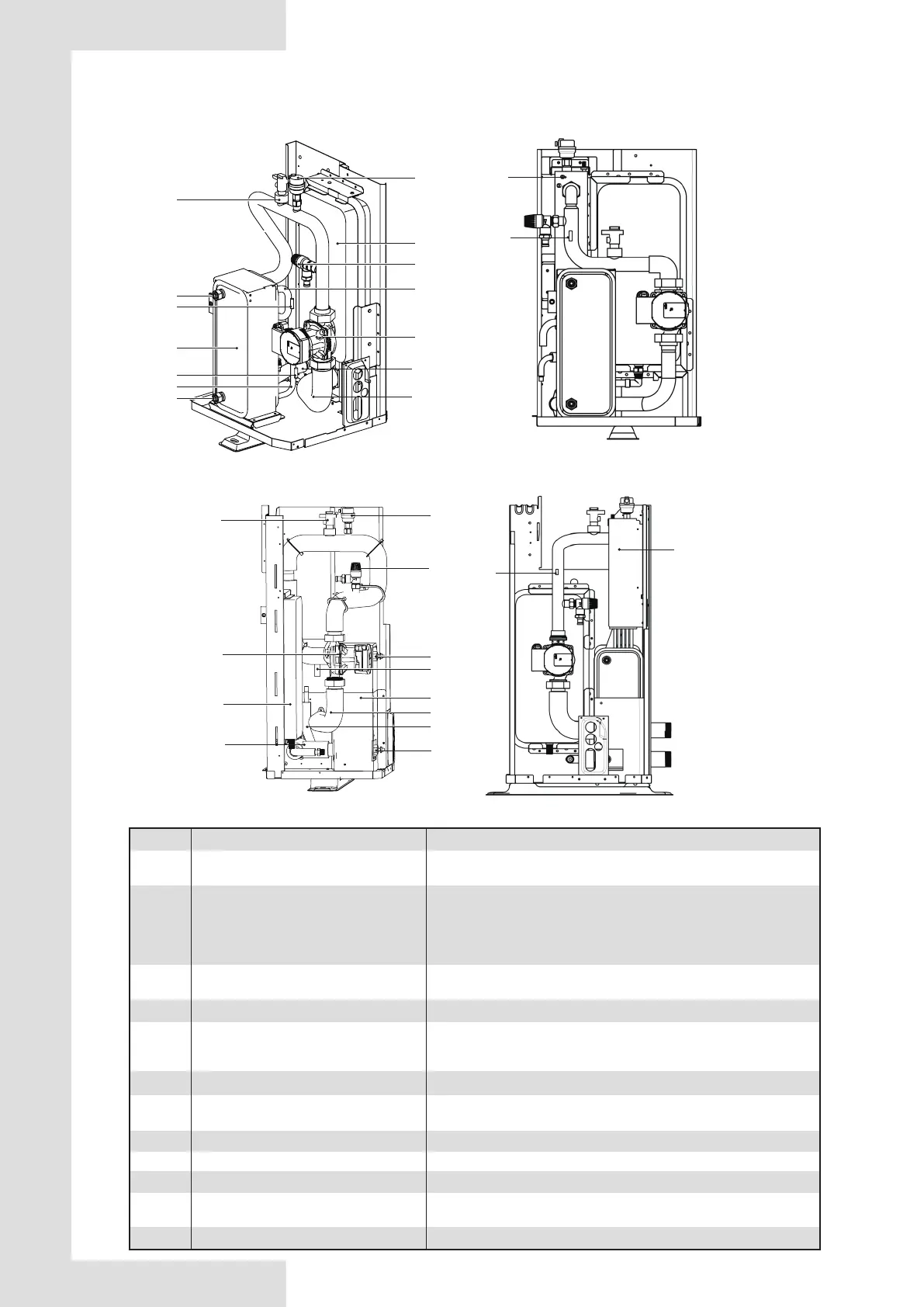
Air purge valve
Backup heater(optional)
Expansion vessel
Refrigerant gas pipe
Temperature sensor
Refrigerant liquid pipe
Flow switch
Pump
Plate heat exchanger
Water outlet pipe
Pressure relief valve
Water inlet pipe
Explaination
Remaining air in the water circuit will be automatically removes
air from the water circuit.
Provides additional heating capacity when the heating
capacity of the heat pump is insufficient due to very low
outdoor temperature. Also protects the external water piping
from freezing.
Balances water system pressure.
Four temperature sensors determine the water and refrigerant
temperature at various points in the water circuit.
5.1-T2B; 5.2-T2; 5.3-T1(optional); 5.4-TW_out; 5.5-TW_in
Detects water flow rate to protect compressor and water pump
in the event of insufficient water flow.
Circulates water in the water circuit.
Transfer heat from the refrigerant to the water.
Prevents excessive water pressure by opening at 3 bar and
discharging water from the water circuit.
/
/
/
/
9.2 Main components
9.2.1 Hydraulic module
4/6 kW with backup heater(optional)
2
5.3
1
7
3
4
5.4
5.5
5.1
5.2
6
8
9
12
11
10
4/6 kW without backup heater
8~16 kW without backup heater 8~16 kW with backup heater(optional)
1
4
5.4
5.5
6
9
11
10
3
7
8
12
2
5.3

 Loading...


