18
9 OVERVIEW OF THE UNIT
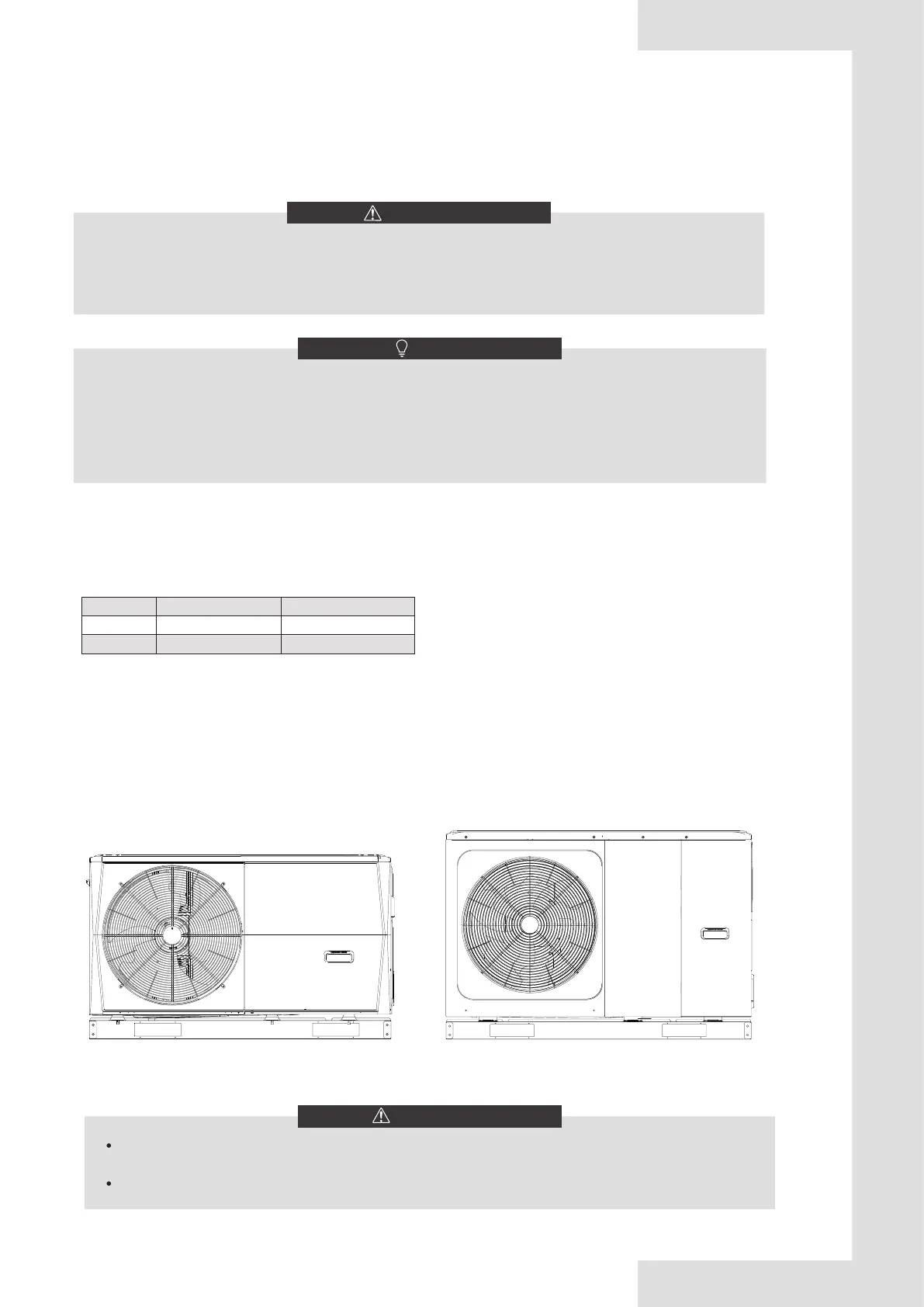
9.1 Disassembling the unit
WARNING
Switch off all power — i.e. unit power supply and backup heater and domestic hot water tank power supply (if
applicable) — before removing doors 1 and 2.
Parts inside the unit may be hot.
Door 1
To access to the compressor and
electrical parts.
Door 1
Door 2
To access to the hydraulic
compartment and electrical parts.
To access to the compressor and
electrical parts and hydraulic
compartment
4/6kW
8/10/12/14/16kW
1 1 2
The floor heating loops require a lower water temperature in heating mode compared to radiators. To achieve
these two set points, a mixing station is used to adapt the water temperature according to requirements of the floor
heating loops. The radiators are directly connected to the unit water circuit and the floor heating loops are after
the mixing station. The mixing station is controlled by the unit.
1) Make sure to connect the SV2/SV3 terminals in the wired controller correctly,please refer to 9.7.6/2) for 3-way
valve SV1,SV2,SV3.
2) Thermostat wires to the correct terminals and to configure the ROOM THERMOSTAT in the wired controller
correctly . Wiring of the room thermostat should follow method A/B/C as described in 9.7.6 "Connection for other
components / 6) For room thermostat".
CAUTION
NOTE
1) Zone 2 can only operate in heating mode. When cooling mode is set on user interface and zone 1 is OFF, “CL”
in zone 2 closes, system still keeps “OFF”. While installation, the wiring of thermostats for zone 1 and zone 2
must be correct.
2) Drainage valve(9) must be installed at the lowest position of the piping system.
The Balance tank volume requirement:
NO. model Balance tank (L)
1 4~10 kW ≥25
2 12~16 kW ≥40

 Loading...


